
Data Sheet

5/5/2018 DS1101W Platform
http://docs.tibbo.com/taiko/index.html?platform_ds1101w.htm 1/2
DS1101W Platform
Top Previous Next
Memory space and key info
RAM 22,271 bytes for application variables and data
Flash 983,040 bytes for application and data storage (shared flash memory)
EEPROM 2040 bytes for application data
TiOS firmware version [V3.60]
Platform type 16-bit platform
Clock frequency (CLOCK) and clock control PLL on (def): 88.4736Mhz, PLL off: 11.0592Mhz
Available network interfaces
Ethernet (net.), Wi-Fi (wln.)
,
PPP (ppp.),
PPPoE (pppoe.)
(1)
GPIO type
Unidirectional
(2)
UART limitations Max practical baudrate ~921600
Serial port FIFOs 16 byte for TX, 16 bytes for RX
Serial port line configuration Depends on the serial port mode
Serial port interrupts and io.intenabled Independent
RTS/CTS remapping
Supported
(3)
ADC N/A
GA1000 lines remapping
Supported
(4)
Beep.divider calculation beep.divider=CLOCK / (2 * desired_frq)
Recommended buzzer frequency divider 2700Hz, beep.divider = 16200 (with PLL ON)
Display type selection and line remapping Type selection and line remapping supported,
but the hardware dictates the use of "Solomon
SSD1305" driver and a predefined control line
arrangement
Special configuration section of the EEPROM 28 bytes for MAC and device password storage
Device serial number 128 bytes: 64 OTP bytes + 64 fixed bytes
Flash memory configuration Shared
Self-upgrades for the Tibbo-BASIC/C app. Supported through fd.copyfirmware,
fd.copyfirmwarelzo, and
fd.copyfirmwarefromfile methods
Status LEDs /LED control lines Green status (SG) LED
Red status (SR) LED
Yellow Ethernet status (EY) LED
An LED bar consisting of five blue LEDs
Debug communications Ethernet / UDP Broadcast transport
Ethernet /WinPCap transport
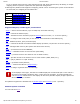
Comments:
1. The sock.allowedinterfaces property refers to the Ethernet interface as "NET", Wi-Fi — as "WLN", PPP
— as "PPP", and PPPoE — as "PPPOE". Sock.targetinterface and sock.currentinterface properties rely on
the pl_sock_interfaces enum, whose members differ depending on the platform.
2. Surrounding board hardware dictates which GPIO lines must be used as inputs and which — as
outputs.
3. The hardware of this platform supports serial channels, which means that CTS/RTS and DTR/DSR pairs
of the DB9 connector can also be used as RX/TX pairs of additional serial channels. Therefore, it is up