
User's Manual


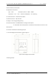
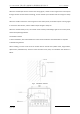
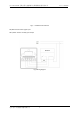
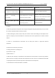
Table Of Contents
- I.General
- II.Features
- 1. Adopting 470MHz wireless communication technolo
- 2. With battery low-voltage detection function, it
- 3. Use microprocessor to realize signal processing
- III.Technical specifications
- IV.Structure characteristics and working principle
- When the module input terminal receives the closin
- When the module receives the control signal from t
- When the module battery is low, the module sends a
- 3.Installation method
- V.Test
- Warning: Please make sure that the polarity of the
- 1. After the module is installed and tested every
- 2. Alarm test: After the networking is successful,
- 3. During the test, the unqualified modules are re
- VI. Use and operation
- VII. General failure and repair
- VIII. Notes
- 1. After the signal passes through the wall, the s
- 2. When installing the product, keep it away from
- 3. Install in a low-interference environment and f

JTY-GM-TC5401W 无线点型光电感烟火灾探测器安装使用说明书 Ver1.0 202010
辽宁•营口天成消防设备有限公司
7
4. Output start: when the module receives the control signal from the control panel, the module outputs
a passive close signal, which can be connected to other devices, and the module output red light is
always on.
5. Device reset: power on again.
6. Restore factory settings: After the module is connected to the network, when it is powered on again,
the output red light will be on for 10s. During this period, you can restore the factory settings by pressing
the setting button 5 times. The factory restoration is successful, and the output red light will flash 3
times.
7. Whether the output is detected or not: After the module is connected to the network, when it is
powered on again, the output red light will stay on for 10s. During this period, click the setting button 3
times to turn off the output fault detection, and the yellow light will flash 3 times when the setting is
successful. (Note: If the output failure detection has been set to turn off, the above operation can turn on
the failure detection)
VII. General failure and repair
General faults and their solutions are shown in the table below:
Fault
Reason
Solution
Faulty yellow light flashes once
every 48s
Low battery
Change the battery
Faulty yellow light flashes twice
every 48s
Too far away from the controller or
interference sources nearby
Move the module near the controller
to eliminate the source of interference
Faulty yellow light flashes three
times every 48s
A fault is detected at the input of
the module
10K resistors are serially connected to
the input of the module
Faulty yellow light flashes four
times every 48s
A fault is detected at the output of
the module
Input 24V power at the output of the
module
Faulty yellow light flashes five
The module detects the
Refer to the above solutions to solve