
Installation Manual

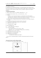
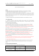
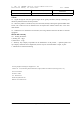
Table Of Contents

J- SAP -TC SB5406W Wireless Digital Manual Call Point
Installation making use instructions Ver1.1 202011
YINGKOU TIANCHENG FIRE PROTECTION EQUIPMENT CO., LTD
4
Figure 3 Installation hole distance
6. Test
Warning: Please make sure that the polarity of the battery is correct before proceeding.
1 . Alarm button after the installation and every year in the course of the test.
2 . Alarm Test: After a successful network, optionally an alarm button , it artificial alarm condition
(please off linkage function fire, to avoid unnecessary alarm linkage), after the end of the test, using a
dedicated reset key that the alarm button to reset , And notify the relevant management department to
restore the system to normal.
3 . During the test failed probe by "general faults and maintenance" and "maintenance" to resolve.
7.Use and operation
7.1 . Network is provided: the alarm button preceded network segment of the network apparatus
provided in the control panel a menu of network setting interface , arranged according to the actual
situation alarm button network segment.
7.2 . Network equipment and network back:
A) Network Operation: When the control panel is in the "wireless enrollment interface", and alarm
button in a non-network state, by pressing the fast network button three times, while the green light
flashes 3 times , alarm button sending an application to the network control panel, After the application
is successful, the total number of network access displayed by the control panel + 1 .
B) disconnection operation: when the control panel is in the "wireless enrollment interface", and alarm
button in a state that has accessed, rapid continuous press Network button three times, while the
green light flashes 3 times after , alarm button is sent to the control panel back network application, the
application is successful , the control panel displays the total number of network exit + 1 .
C) the state detection: The alarm button on the power, pressing a key network times, the green light
flashes a secondary control panel as the control panel displays alarm button loop address
number indicates that the alarm button has accessed successfully, otherwise the alarm button is not
Network access status.
7.3 . Device Alarm: When the alarm button is pressed , the red constant light, alarm button alarm signal
is transmitted wirelessly to the control panel, the control panel in response to the alarm signal .
7.4 . Device Reset: special key reset .
7.5 . Restore factory settings: alarm button after the network, when the reset or power on, the alarm
lamp long bright 10s , during which the batter networking button five times to restore the factory
settings.
8. General faults and maintenance
The general faults and their solutions are shown in the following table:
Failure phenomenon reason Solution
The control panel has no status
prompt after the device alarms
The device is not connected to the
network
Restart the network operation
Device networking is
unsuccessful
Too far away from the control
panel or interference sources
Move the device near the control
panel, reconnect to the network