
Installation Instructions
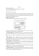
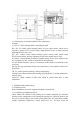
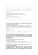

Figure 2-4
2.3.2 Description of external terminals of the control panel
In which:
L, n, PE: AC 220V terminal and AC grounding terminal.
HJ+, HJ-: fire alarm output terminals (there are two output modes, which can be
selected by jumper. Active control output, output DC24V in case of alarm, and stop
outputting DC24V after reset).
SG+, SG-: sounder control output terminals (active control points, which output
DC24V when starting, and stop outputting DC24V after manual stop or reset).
A1 and B1: connect RS485 terminals of graphic display device in fire control room.
A1 is terminal A of 485, and B2 is terminal B of 485 (optional).
A2, B2: RS485 terminals, with A1 as terminal A of 485 and B1 as terminal B of 485
(reserved).
Qn, Gn, Hn: output terminals of three-wire special line, n: route number of three-wire
special line.
CH, CL: control panel networking CAN bus with polarity.
COM QD: the output terminal of the starting relay. When there is starting information,
the relay starts.
COM GZ: output terminal of fault relay, which is started when there is fault
information.
3. Installation and commissioning
3.1 Unpacking check
Before installation, the on-site equipment should be checked first.
3.1.1 Engineering configuration check
Check whether the contents of the packing list of control equipment are consistent
with the project configuration. After opening the packing box, check the goods in the
box one by one according to the contents of the packing list. The main check contents
include: installation instructions, control panel keys, etc., and then check the