
Installation Instructions
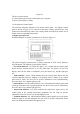
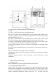
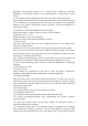

Figure 2-3
The loop control panel has 18 manual fire starting points, and each starting point has a
key, two indicators and a label. Among them, the key is the start/stop control key. If
the control key of a certain unit is pressed, the control command will be sent out.
When the start-up state of the equipment is received, the command light of the unit
will light up (red). If the controlled equipment starts and sends out a feedback signal,
the answer indicator will light up (red). The user can write the device name
corresponding to each key on the device label, and then fix it on the manual disk
together with the diaphragm.
3) direct control panel
Schematic diagram of special line control area is shown in Figure 2-3.
The dedicated line control panel has six manual starting points, and each starting point
has a key, three indicators and a label. Among them, the key is the start/stop control
key. If the control key of a unit is pressed, the start indicator of the unit will light up
(red) and a control command will be issued. If the controlled equipment responds, the
feedback indicator will light up (red). When the external wiring breaks or shorts, the
fault indicator will light up (yellow). The user can write the device name
corresponding to each key on the device label, and then fix it on the manual disk
together with the diaphragm.
2.3 description of internal structure and connection
2.3.1 description of the control panel structure
The control box is the core part of the control panel, which is mainly composed of
three parts: main board, circuit main board and circuit substation board.