
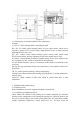
Installation Instructions
·
Main power operating indicator: green, which lights when the control panel is
powered by AC220V power supply.
·
Standby power operating light: green. When the control panel is powered by
standby power, this light will light up.
·
Disable indicator: yellow. When an external device (detector, module, etc.) fails, it
can be disabled. After repair or replacement, the device can be restored by using the
function of removing disable. This indicator comes on when disable equipment exists.
·
Sounder start indicator: red. When the sounder output contact has 24V output, this
indicator will light up. When there is no 24V output at the sounder output contact, this
indicator goes out.
·
Sounder fault indicator: yellow. When the sounder output contact is brEnteren or
short-circuited, this indicator lights up. After the fault is recovered, this indicator goes
out.
·
sounder disable indicator: yellow, which lights when the sounder output contact is
disabled.
·
Transmission fault light: yellow, which lights when the connecting line with
transmission equipment is open, short-circuited or abnormal in communication. After
communication returns to normal, this light goes out.
·
Transmission status indicator: red. When information such as fire alarm and fault
occurs, the control panel sends information to the transmission equipment, and the
light flashes. When the control panel receives the reply information from the
transmission equipment, the light is always on.
·
Transmission disable indicator: yellow, which lights when transmission is
disabled.
·
Manual permission: green; when manual permission is started, this light is on.
·
Automatic permission: green; when automatic permission is started, this light is on.
Self-test indicator: yellow, which lights when the system is in self-test state.
·
Mute indicator: green. When the control panel sounds an alarm, press the "mute"
key to turn on the mute indicator, and the speaker stops sounding an alarm. When a
new alarm occurs, the mute indicator goes out and the alarm sounds again.
·
System fault: yellow. When the system program can't work normally, this indicators
on.
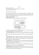
See the third part "System Application" for the function of each operation key.
2) loop control panel
The schematic diagram of loop control area is shown in Figure 2-3.