
Installation Instructions
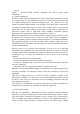
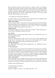
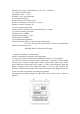
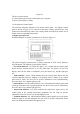
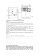
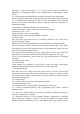

Figure 2-1
The above picture shows:
(1) control panel part (2) loop control panel part (18 points)
(3) direct control panel (6 loops)
2.2 Description of control panel
The structural schematic diagram of fire alarm control panel \ fire linkage control
panel is shown in Figure 2-2: it consists of three parts: display operation area, loop
control area and multi-loop control area, among which the multi-loop control area is
shown in the corresponding instructions.
1) display operation area
Schematic diagram of display operation area is shown in figure 2-2.
Figure 2-2
The panel of display operation area is mainly composed of LCD screen, indicator,
keys and printer. The indicator is described as follows:
·
Fire alarm indicator: red. When this light is on, it means that the control panel
detects that the external detector is in a fire alarm state. For details, see the LCD
display. After the fire alarm is eliminated, press the "Reset" key, and the light goes
out.
·
Fault indicator: yellow, which indicates that the control panel detects that the
external equipment (detector, module or fire display panel) is faulty, or the control
panel itself is faulty. See the LCD for specific information. After troubleshooting,
press the "Reset" key, and the light goes out.
·
Start indicator: red. When this indicator is on, it means that the control panel sends
a start-up command to the external equipment. See the LCD for specific information.
Press the "Reset" key, and the light goes out.
·
Supervision indicator: red, which indicates the supervision signal sent by the
control panel to the external supervision equipment. See the LCD for specific
information. Press the "Reset" key, and the light goes out.
·
Feedback indicator: red, which indicates that the control panel receives the action
feedback signal of external equipment. See the LCD for specific information. When
there is no feedback information, this light goes out.