
Installation Instructions

Backup power supply: lead-acid battery 12V/3.3Ah 2 batteries.
1.4.2 Operating environment
Temperature: -10℃ ~+55℃.
Humidity: ≤95%, non-condensing.
1.4.3 Equipment capacity
Number of loops: two wireless loops.
Number of components in each loop: 32 points.
Number of network segments: 29.
1.4.4 wire system requirements
CAN bus: RVS twisted pair with cross-sectional area ≥ 1.0mm.
1.4.5 Radio frequency parameters
Transmit power: < 20dBm
Communication distance: ≤50m
Frequency band: 470MHz
1.4.6 Implementation standards
Executive standard: GB4717-2005 fire alarm control panel
GA 1151-2014 general requirements for wireless communication
function of fire alarm system
GB16806-2006 fire linkage control system
2. Structure, installation, commissioning
Chapter 2 Instructions of structure and configuration
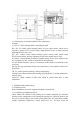
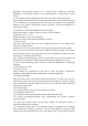
2.1 Overview of Typical Configuration and Internal Structure of Control Panel
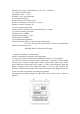
The JB-TB-TC5126W wireless fire alarm control panel is installed in wall-mounted
structure, and its typical configuration includes: main control panel, loop control
panel, multi-loop control panel, power supply, etc. This system integrates alarm and
linkage. Through wireless and multi-loop control, it can not only complete the
functions of alarm and start/stop control of general fire-protection equipment, but also
realize the control of important fire-protection equipment.
The appearance schematic diagram of JB-TB-TC5126W control panel is shown in
figure 2-1: