
Installation Instructions

6.4 Structural Features of Direct system
6.4.1. Description of panel
(1) Fault indicator: yellow. When the external control line of this road is
short-circuited or open-circuited, the light will come on.
(2) Start indicator: red, which lights up after the control command is issued.
(3) Feedback indicator: red. When the controlled equipment is in response to the
command, the feedback indicator lights up.
6.4.2. Description of direct control panel
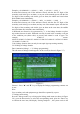
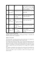
The structural diagram of the output part of 6.4.2.1 Special Line is shown in Figure
6-1:
Figure 6-1
In which:
Q, G: Start output terminal, and output DC24V when starting. Output current is less
than 200mA, load is signal relay, and coil resistance is 0.5-2K.
H, g: answer signal input terminal of external equipment, which is the answer signal
when passive closing, and the terminal resistance is 4.7K
Wiring requirements of 6.4.2.4: BV copper conductor should be used for wiring of
multi-wire external control points, with cross-sectional area ≥ 1.0mm
2
.
Chapter 7
7. Fault and Abnormal information processing and Regular Check
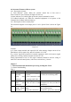
7.1 General fault handling
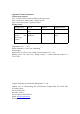
Table 1
No.
Fault
Reason
Solution
1
No display or
abnormal
display after
starting up
A. The power supply is
abnormal
B. Poor connection with
the display panel cable
A. Check the 24V power supply
B. Check the connecting cable
2
"main power
failure" after
starting up
A. No AC power
B. The AC fuse is burnt
out
A. Check and connect the AC wire
B. Replace AC fuse (see label for
parameters)
3
after starting up,
"standby failure"
is displayed.
A. The insurance is
broken
B. Poor line connection
A. Change the safety tube (see
label for parameters)
B. Open the power box and check