
Installation Instructions

modules, etc. All these external devices need to be coded. The codes of these devices
include the original address and the on-site code.
"Channel" is filled with "01" by default for equipment without channel.
The "user secondary number" consists of eight digits from 0 to 9, which is a group of
numbers defined artificially to express the specific on-site environment where the
equipment is located. Users can easily know the location of the coded equipment and
other information related to the location through this code. General provisions for user
coding are as follows:
The first and second digits correspond to the building number where the equipment is
located, and the value range is 0-99. The so-called building number refers to a
relatively independent building. For example, a garden community consists of several
office buildings, and each building can be regarded as a building.
The third digit corresponds to the area code of the building where the equipment is
located, and the value range is 0-9. If a building has three units, each unit is a district.
The fourth and fifth digits are floor numbers. To facilitate the definition of equipment
in the underground part of the building, it is stipulated that the underground floor is 99,
the underground floor is 98, and so on.
The sixth, seventh and eighth bits correspond to the room number where the bus
system equipment is located or other codes that can identify features.
The equipment type in the "Equipment Type" equipment type table does not need to
be filled in.
"Annotation information" means the location of the equipment or other relevant
Chinese character prompt information. This item can be composed of 10 Chinese
characters or 20 characters at most, or the combination of Chinese characters and
characters can not exceed 20 characters in length.
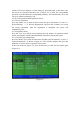
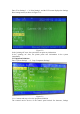
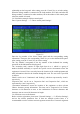
5.3.2 Definition Example of General Equipment of Loop Control Panel
Enter "System Settings" → "2. Loop Control Panel Settings".
Figure 5-4
Enter the address number of the bus disk and the address of the corresponding linkage
module. Then press the corresponding "Confirm" key to set the corresponding linkage