
Users Manual

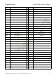

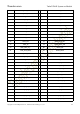


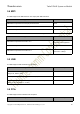
Table Of Contents
- 2Functional Overview
- 3Interfaces Description
- 3.1Interfaces Parameter Definitions
- 3.2Interfaces Detail Description
- 3.2.1Power Supply Interface
- 3.2.2Touchscreen Interface
- 3.2.3Display Interface
- 3.2.4Camera Interfaces
- 3.2.5Audio Interface
- 3.2.6USB & DisplayPort Interface
- 3.2.7 PCIe Interface
- 3.2.8 SSC Interface
- 3.2.9 SDIO Interface
- 3.2.10 QUP Interface
- 3.2.11Power on Interface
- 3.2.12Reset Interface
- 3.2.13 Keys Interface
- 3.2.14 Sensor Interrupt Interface
- 3.2.15Debug UART Interface
- 3.2.16Battery Interface
- 3.2.17ADCs Interface
- 3.2.18 PWMs and LED Current Driver Interface
- 3.2.19Antenna Interface
- 4Connector PIN Summary
- 5Electrical Characteristics

Thundercomm TurboX D845 System on Module
Copyright © 2018 All Rights Reserved , Thundercomm Technology Co., Ltd.
37
5 Electrical Characteristics
5.1 Absolute Maximum Ratings
The SOM needs to be desinged in the operatin conditions which is shown as below table.
Parameter Min Max Units
Input Power voltage
USB_VBUS -0.3 28 V
VBAT -0.5 6 V
VBATT_CONN_VSENSE_P,
VBATT_CONN_VSENSE_M,
RSENSE_EXT_M,
RSENSE_EXT_P
-0.5 6 V
ESD
ESD-HBM model rating ±2k KV
ESD-CDM model rating ±4k KV
Table 5.1- 1 Absolute rating condition
Notes: for the ESD, it will be valid and available only when the module is fully tested and approved in the Initial
Production stage.
5.2 Operating Conditions
The SOM needs to be desinged in the operatin conditons which is shown as below table.
Parameters Min Typical Max Units
Input Power voltage
USB_VBUS +3.6 5 +13.2 V
VBAT +3.6 3.8 +4.8 V
VBAT 3 A
VBATT_CONN_VSENSE_P,
VBATT_CONN_VSENSE_M,
RSENSE_EXT_M,
+3.6 3.8 +4.8 V