
Users Manual
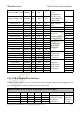
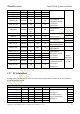
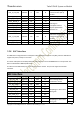

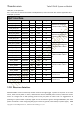
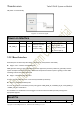
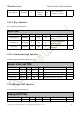

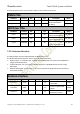
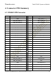
Table Of Contents
- 2Functional Overview
- 3Interfaces Description
- 3.1Interfaces Parameter Definitions
- 3.2Interfaces Detail Description
- 3.2.1Power Supply Interface
- 3.2.2Touchscreen Interface
- 3.2.3Display Interface
- 3.2.4Camera Interfaces
- 3.2.5Audio Interface
- 3.2.6USB & DisplayPort Interface
- 3.2.7 PCIe Interface
- 3.2.8 SSC Interface
- 3.2.9 SDIO Interface
- 3.2.10 QUP Interface
- 3.2.11Power on Interface
- 3.2.12Reset Interface
- 3.2.13 Keys Interface
- 3.2.14 Sensor Interrupt Interface
- 3.2.15Debug UART Interface
- 3.2.16Battery Interface
- 3.2.17ADCs Interface
- 3.2.18 PWMs and LED Current Driver Interface
- 3.2.19Antenna Interface
- 4Connector PIN Summary
- 5Electrical Characteristics

Thundercomm TurboX D845 System on Module
Copyright © 2018 All Rights Reserved , Thundercomm Technology Co., Ltd.
28
use for debug
MSM_UART_TX CON2402 138
PX3
DO
Table 3.2- 15 Debug UART interface definition
3.2.16 Battery Interface
This is dedicate for battery interface, major for monitoring battery status, inserting and voltage detect.
Battery PINs
PIN Name Location PIN
Voltage
Type Description Notes
VBATT_CONN_VSENSE_P CON2402 164 VBATT AI
Battery voltage sense
positive input signal
VBATT_CONN_VSENSE_M CON2402 166 VBATT AI
Battery voltage sense
negative input signal
IBATT_SENSE_P CON2402 158 VBATT AI
Battery current sense
positive input signal
IBATT_SENSE_M CON2402 160 VBATT AI
Battery current sense
negative input signal
BATT_THERM CON2402 144
BATT_THERM
_BIAS=2.7V
AI
Battery temperature
sense input signal
Table 3.2- 16 Battery interface definition
3.2.17 ADCs Interface
The ADC input signal use as analog multiplexer function.
ADCs PINs
PIN Name Location PIN
Voltage
Type Description Notes
ADC_IN_5V CON2402 152 MV AI
ADC input, can be
configured as 1.8V or 5V
ADC_IN_1P8V CON2402 154 LV AI
ADC input, can be
configured as 1.8V
Table 3.2- 17 MPPs interface definition
3.2.18 PWMs and LED Current Driver Interface
The SOM support dual PWM output and dual LED Current Driver, all PWM output by Light Pulse Generators.
LED Current Driver PINs can be used for different events, they are separate controller. Independently
programmable duty cycle and period via LPGs (6-or 9-bit resolution) for digital dimming.
Flash or blinking with register-selectable durations of ON-time from 0 to 1 second, in ≤ 0.05-second steps,