
Users Manual Part 2
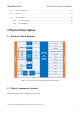
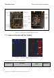

Table Of Contents
- 1 Physical Description
- 2 Interfaces Description
- 2.1 Interfaces Parameter Definitions
- 2.2 Interfaces Detail Description
- 2.2.1 Power Supply Interface
- 2.2.2 Touchscreen Interface
- 2.2.3 Display Interface
- 2.2.4 Camera Interfaces
- 2.2.5 Audio Interface
- 2.2.6 USB & DisplayPort Interface
- 2.2.7 PCIe Interface
- 2.2.8 SSC Interface
- 2.2.9 SDIO Interface
- 2.2.10 QUP Interface
- 2.2.11 Power on Interface
- 2.2.12 Reset Interface
- 2.2.13 Keys Interface
- 2.2.14 Sensor Interrupt Interface
- 2.2.15 Debug UART Interface
- 2.2.16 Battery Interface
- 2.2.17 ADCs Interface
- 2.2.18 PWMs and LED Current Driver Interface
- 2.2.19 Antenna Interface
- 3 Connector PIN Summary
- 4 Electrical Characteristics

Thundercomm TurboX C865 System on Module
Copyright © 2018 All Rights Reserved, Thundercomm Technology Co., Ltd.
6
4.17 Power Consumption ........................................................................................................................... 47
4.18 Thermal .............................................................................................................................................. 47
4.19 RF Performance ................................................................................................................................. 48
4.19.1 Wi-Fi Performance ..................................................................................................................... 48
4.19.2 BT Performance ......................................................................................................................... 55
1 Physical Description
1.1 Hardware Block Diagram
Figure 1.1-1 TurboX C865 SOM Hardware System Block Diagram
1.2 Major Components Location
TurboX C865 SOM’s major components as below map.