
Users Manual Part 2
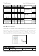

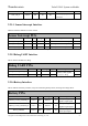
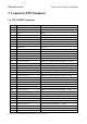
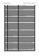
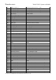
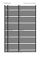
Table Of Contents
- 1 Physical Description
- 2 Interfaces Description
- 2.1 Interfaces Parameter Definitions
- 2.2 Interfaces Detail Description
- 2.2.1 Power Supply Interface
- 2.2.2 Touchscreen Interface
- 2.2.3 Display Interface
- 2.2.4 Camera Interfaces
- 2.2.5 Audio Interface
- 2.2.6 USB & DisplayPort Interface
- 2.2.7 PCIe Interface
- 2.2.8 SSC Interface
- 2.2.9 SDIO Interface
- 2.2.10 QUP Interface
- 2.2.11 Power on Interface
- 2.2.12 Reset Interface
- 2.2.13 Keys Interface
- 2.2.14 Sensor Interrupt Interface
- 2.2.15 Debug UART Interface
- 2.2.16 Battery Interface
- 2.2.17 ADCs Interface
- 2.2.18 PWMs and LED Current Driver Interface
- 2.2.19 Antenna Interface
- 3 Connector PIN Summary
- 4 Electrical Characteristics

Thundercomm TurboX C865 System on Module
Copyright © 2018 All Rights Reserved, Thundercomm Technology Co., Ltd.
2
connect to positive port
Table 3.2-11 PWMs and LED Current Driver interface definition
2.2.19 Antenna Interface
The SOM provides the fully-integrated WLAN and Bluetooth function.
The WLAN and Bluetooth share the antenna port with 50ohm impedance.
WLAN supports 2 × 2 multiple input, multiple output (MIMO) with two spatial streams IEEE802.11
a/b/g/n/ac/ax WLAN standards.
Supports Bluetooth 5.1 + HS enabling seamless integration of WLAN/Bluetooth and low energy
technology.
Antenna interface
Name
Location
PIN
Voltage
Type Description
Notes
Antenna 1 J1501
IO
Antenna 1 supports WIFI
2.4G/5G &BT
Chain0
Antenna 2 J5907
IO
Antenna 2 supports WIFI
2.4G/5G
Chain1
Table 3.2-12 Antenna interface definition