
Users Manual Part 2
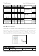

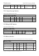
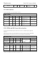
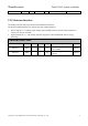
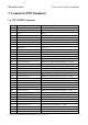
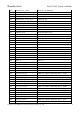
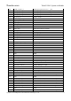
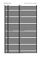
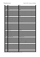
Table Of Contents
- 1 Physical Description
- 2 Interfaces Description
- 2.1 Interfaces Parameter Definitions
- 2.2 Interfaces Detail Description
- 2.2.1 Power Supply Interface
- 2.2.2 Touchscreen Interface
- 2.2.3 Display Interface
- 2.2.4 Camera Interfaces
- 2.2.5 Audio Interface
- 2.2.6 USB & DisplayPort Interface
- 2.2.7 PCIe Interface
- 2.2.8 SSC Interface
- 2.2.9 SDIO Interface
- 2.2.10 QUP Interface
- 2.2.11 Power on Interface
- 2.2.12 Reset Interface
- 2.2.13 Keys Interface
- 2.2.14 Sensor Interrupt Interface
- 2.2.15 Debug UART Interface
- 2.2.16 Battery Interface
- 2.2.17 ADCs Interface
- 2.2.18 PWMs and LED Current Driver Interface
- 2.2.19 Antenna Interface
- 3 Connector PIN Summary
- 4 Electrical Characteristics

Thundercomm TurboX C865 System on Module
Copyright © 2018 All Rights Reserved, Thundercomm Technology Co., Ltd.
2
GPIO53 CON1 F37
P3
IO
configured to GPIO or
SPI or I2C
GPIO54 CON1 C42
P3
IO
GPIO55 CON1 F36
P3
IO
GPIO56 CON1 G35
P3
IO
QUP18 can be
configured to GPIO or
SPI or I2C
GPIO57 CON1 F34
P3
IO
GPIO58 CON1 G34
P3
IO
GPIO59 CON1 G33
P3
IO
GPIO8 CON1 A46
P3
IO
QUP4 can be configured
to GPIO or I2C
GPIO9 CON1 D35
P3
IO
RGB_1V2_EN CON1 K40
P3
IO
QUP2 can be configured
to GPIO or I2C
GPIO 115
GPIO 116
CON1 K41
P3
IO GPIO 116
GPIO125 CON1 A9
P3
IO
QUP9 can be configured
to GPIO or I2C
6DOF_ULPM CON1 B45
P3
IO GPIO 126
WSA2_EN CON1 B41
P3
IO
QUP10 can be
configured to GPIO or
I2C
GPIO 129
6DOF_L_RST CON1 B44
P3
IO GPIO 130
Table 3.2-5 QUP interface definition
2.2.11 Power on Interface
Dedicated PMIC circuits continuously monitor events that might trigger a power-on sequence. If an event occurs,
these circuits power on the IC, determine the device’s available power sources, enable the correct source. It is
longer than 1s with pressing power-on key, for power on event. And it is suggested for 3s powering on system.
Power on/off key signal can be connected to ground through CON1.A45; the other power on method is: when
using CBL_PWR_N pin connect to ground, insert battery or power supply,SOM will power on automatically.
Figure 3.2-1 Power on signal
Power on Interface
PIN Name
Location
PIN
Voltage
Typ
e
Description
Notes