
Users Manual Part 2
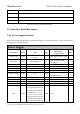
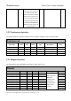
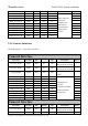
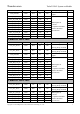
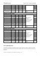
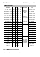
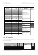
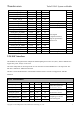
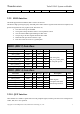
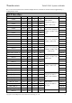
Table Of Contents
- 1 Physical Description
- 2 Interfaces Description
- 2.1 Interfaces Parameter Definitions
- 2.2 Interfaces Detail Description
- 2.2.1 Power Supply Interface
- 2.2.2 Touchscreen Interface
- 2.2.3 Display Interface
- 2.2.4 Camera Interfaces
- 2.2.5 Audio Interface
- 2.2.6 USB & DisplayPort Interface
- 2.2.7 PCIe Interface
- 2.2.8 SSC Interface
- 2.2.9 SDIO Interface
- 2.2.10 QUP Interface
- 2.2.11 Power on Interface
- 2.2.12 Reset Interface
- 2.2.13 Keys Interface
- 2.2.14 Sensor Interrupt Interface
- 2.2.15 Debug UART Interface
- 2.2.16 Battery Interface
- 2.2.17 ADCs Interface
- 2.2.18 PWMs and LED Current Driver Interface
- 2.2.19 Antenna Interface
- 3 Connector PIN Summary
- 4 Electrical Characteristics

Thundercomm TurboX C865 System on Module
Copyright © 2018 All Rights Reserved, Thundercomm Technology Co., Ltd.
1
PD Contains an internal pull-down device
PU Contains an internal pull-up device
P3 Power group 3, it is 1.8V.
P2 SDC Power group 2, it is 1.8V or 2.95V.
Table 2.1-1 Interfaces parameter definitions
2.2 Interfaces Detail Description
2.2.1 Power Supply Interface
Below table describes all interfaces of SOM Power Supply. For the detail parameter request, please refer the
chapter on Electrical specifications.
Power Supply
PIN Name Conn. PIN Type
Description,
V_typ@I_rated
Note
VBAT_CON
CON1
J47,J48,J49,J50,K47,K48,K
49,K50
PI Power supply input for SOM
USB_VBUS CON1 E47,E48,E49,E50 PO
USB output during USB-
OTG operation.
VREG_L11C_3P3
CON1
A49
PO
LDO, 3.1V@600mA
VREG_L9C_2P96
CON1
A50
PO
LDO, 2.96V@600mA
VREG_L5C_1P8
CON1
B4, B5
PO
LDO, 1.8V@150mA
VREG_L8C_1P8
CON1
B42
PO
LDO, 1.8V@150mA
VREG_IO_1P8 CON1 B43 PO
VREG SPMI output for
SPMI PAD and PX0
VREG_L2A_3P1
CON1
D43
PO
LDO, 3.1V@150mA
VREG_S4A_1P8
CON1
D45, D46
PO
BUCK, 1.8V@3500mA
VREG_BOB
CON1
D47, D48
PO
Buck-boost output, 3.3V
VPH_PWR
CON1
D49, D50
PO
Primary system supply node
GND CON1
A1,A3,A5,A12,A14,A16,A
18,A20,A22,A24,A26,A28,
A30,A32,A34,A36,B2,B3,
B48,B49,B50,C1,C3,C11,C
13,C15,C17,C19,C21,C23,
C25,C27,C29,C31,C33,C35
,C4,C48,C49,C50,D2,D4,D
12,D14,D16,D18,D20,D22,
GND GND