Empowering Every IoT Device with Our Technology Qualcomm® Robotics RB5 Development Kit Hardware User Manual Rev. V1.1 Mar 12, 2021 Copyright© 2020 Thundercomm Technology Co., Ltd. All rights reserved.
Robotics RB5 Development Kit Hardware User Manual Revision History Revision Date Description 1.0 Sept 24, 2020 1.1 March 12, 2021 Fix typo in Top view in chapter 1.2.1. Remove description about ‘support headset jack’. Fix description for GPIO-B. Initial release. Copyright© 2020 Thundercomm Technology Co., Ltd. All rights reserved.
Robotics RB5 Development Kit Hardware User Manual Table of Contents 1 2 3 Qualcomm® Robotics RB5 Development Kit ..................................................................... 1 1.1 RB5 Development board Key Features ............................................................................................ 1 1.2 Board views ......................................................................................................................................... 3 1.2.1 Top view..............
Robotics RB5 Development Kit Hardware User Manual 4 3.18.1 Ethernet Connector .................................................................................................................. 13 3.18.2 Inertial Sensors .......................................................................................................................... 14 3.18.3 DIP Switch .................................................................................................................................. 14 3.18.
Robotics RB5 Development Kit Hardware User Manual 5.2.1 MIPI CSI ...................................................................................................................................... 31 5.2.2 Clock ........................................................................................................................................... 31 5.2.3 SPI ..........................................................................................................................................
Robotics RB5 Development Kit Hardware User Manual 10.1.2 Board views ............................................................................................................................... 44 10.2 Machine Communication Mezzanine ............................................................................................ 45 10.2.1 Technical specifications ..............................................................................................................
Robotics RB5 Development Kit Hardware User Manual 1 Qualcomm® Robotics RB5 Development Kit Qualcomm® Robotics RB5 Development Kit - the Company's most advanced, integrated, comprehensive offering designed specifically for robotics. Building on the successful Qualcomm® Robotics RB3 platform and its broad adoption in a wide array of robotics and drone products available today, the Qualcomm® Robotics RB5 Development Kit is comprised of an extensive set of hardware, software and development tools.
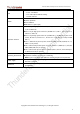
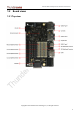
Robotics RB5 Development Kit Hardware User Manual 7 LED indicators: 4 x User controllable LED 2 x For radios (BT and WLAN activity) 1 x Power indicator Power ON Volume Up/Down Button Force USB Boot DIP Switch x 2 (6pin+4pin) HS1:1 x 60 pin high-speed connector (SDC I/F, 1 x 4L MIPI DSI, USB 2.0, CCI I2C x2, 2L+4L-MIPI CSI) HS2:1 x 60 pin high-speed connector (4L-MIPI CSI x 2, SPI x 1, PCIe 3.0 gen3 1L, USB 3.
Robotics RB5 Development Kit Hardware User Manual 1.2 Board views 1.2.1 Top view Copyright© 2020 Thundercomm Technology Co., Ltd. All rights reserved.
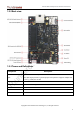
Robotics RB5 Development Kit Hardware User Manual 1.2.2 Back view 1.2.3 Terms and Definitions Component Description Qualcomm Universal Peripheral QUP The QUP engine provides a general-purpose data path that supports multiple mini cores, e.g., UART, I2C and SPI CCI Camera Control Interface SPMI System Power Management Interface Copyright© 2020 Thundercomm Technology Co., Ltd. All rights reserved.
Robotics RB5 Development Kit Hardware User Manual 2 Start the board 2.1 Required equipment Equipment Qualcomm® Description Robotics SOM based on the Qualcomm® QRB5165 processor RB5 Development Kit IO based on 96board requirement Power adapter 12 V with 2500 mA required per 96Boards specification USB to Micro USB cable For serial console interface and ADB, Fastboot commands USB to USB Type C cable For connecting the USB3.
Robotics RB5 Development Kit Hardware User Manual 4. Connect the USB cable Micro-B plug to the USB2.0 debug port (see section 1.2.2, #21), and connect the other end to an available USB port on the host PC. NOTE: Set the Bps/Par/Bits to 115200 8N1 5. Connect the power supply to power connector (see section 1.2.1, #15). 6. Plug the power supply into a power outlet. 7. Press, and hold the power button on the device, and then release it. The green powerup LED should illuminate in a second. 8.
Robotics RB5 Development Kit Hardware User Manual Block diagram part #2 Copyright© 2020 Thundercomm Technology Co., Ltd. All rights reserved.
Robotics RB5 Development Kit Hardware User Manual 3.2 Processor QRB5165 is the new generation Qualcomm® Snapdragon™ premium-tier processor with robotic application. It is designed with the 7 nm process, for superior performance and power efficiency. 3.3 Memory The QRB5165 uses a package on package (PoP) LPDDR5 RAM configuration and discrete UFS3.0 flash memory. The LPDDR5 interface goes directly to the QRB5165 built-in LPDDR controller. The maximum DDR clock is 2750MHz.
Robotics RB5 Development Kit Hardware User Manual The slot is a push-push type with dedicated support for card detect signal (many microSD slots do not have dedicated CD pins, they use DATA3 state as the card detected signal). RB5 uses AP GPIO_77 as the SD_CARD_DET_N. 3.5 Wi-Fi/BT RB5 uses the Qualcomm RF chip QCA6391 solution that integrates two wireless connectivity technologies into a single device. The interfaces are: WLAN-compliant with IEEE 802.
Robotics RB5 Development Kit Hardware User Manual 96Boards specification also calls for a MIPI-DSI interface to be routed to the High Speed Expansion connector. Since the QRB5165 has two MIPI-DSI interface for HDMI, two multiplexing devices (FSA644UCX) are used. Only one interface, HDMI, or the Expansion MIPI-DSI can be active at one time. Control signal,‘DIP_HDMI_SWITCH’, comes from DIP switch#16.
Robotics RB5 Development Kit Hardware User Manual 3.8.1 USB-Host ports The QRB5165 processor includes two USB channels: USB0 (section1.2.1 #5) is for USB Type C. USB1 (through a USB HUB to section1.2.1 #1�) is USB host only ports. RB5 supports below USB host ports by USB HUB mentioned above: Two Type A USB Host 3.0 (super-speed) connector, each with current limit 1.2A. USB 3.0 signals are also routed to high-speed expansion connector HS1&HS2. 3.8.
Robotics RB5 Development Kit Hardware User Manual 3.10 DC-power and Battery Power RB5 power is supplied in one of the following ways: 8 V to 18 V power from a dedicated DC jack 8 V to 18 V power from the DC12V pins on the low-speed expansion connector See Section 6 for details on Robotics RB5 Development Kit DC power implementation. 3.11 DC power Measurements The 96Boards specification calls for support for measuring board power consumption.
Robotics RB5 Development Kit Hardware User Manual Wi-Fi activity LED – RB5 drives this Yellow LED via GPIO_9 from the PMIC (PM8250). BT activity LED – RB5 drives this Blue LED via GPIO_7 from the PMIC (PM8250). Four user LEDs The four user LEDs are surface mount LEDs in 0603 size located next to the two USB Type A connectors and labeled with ‘USER LEDS 3 2 1 0’. RB5 drives three of them by the red, green and blue LED drivers from power management IC PM8150L.
Robotics RB5 Development Kit Hardware User Manual 3.18.2 Inertial Sensors RB5 includes the following inertial sensors. 6-axis accelerometer/gyroscope: INVENSENSE ICM-42688 The SPI interface for ICM-42688 is multiplexing to LS3 by a SPDT, controlled by DIP_SENSOR_SWITCH_IMU. Setting DIP_SENSOR_SWITCH_IMU of DIP switch (section1.2.2 #16) to OFF will enable ICM-42688's SPI communication. 3.18.3 DIP Switch RB5 has two DIP switches (see Section 1.2.2, #16�). DIP switch (section1.2.
Robotics RB5 Development Kit Hardware User Manual 3.18.5 Extra High Speed Expansion Connectors RB5 has 3 high-speed expansion connector. See Section 5 for detail Copyright© 2020 Thundercomm Technology Co., Ltd. All rights reserved.
Robotics RB5 Development Kit Hardware User Manual 4 Low speed Expansion connector 4.
Robotics RB5 Development Kit Hardware User Manual 28 GPIO-F DISPLAY MIPI_ERR_ FG / QUP15 30 GPIO-H DISP_RST_N 33 GPIO-J CAM0_PWDN 34 GPIO-L CAM1_PWDN 36 DC12V 38 DC12V 40 GND 4.1.1 UART The 96Boards specification calls for a 4-wire UART implementation, UART0 and an optional second 2-wire UART, UART1 on the low-speed expansion connector. RB5 implements UART0 as a 4-wire UART that connects directly to the QRB5165 SoC. These signals are driven at 1.8 V.
Robotics RB5 Development Kit Hardware User Manual GPIO G: Connects to GPIO_6 of QRB5165 SoC. GPIO H: Connects to GPIO_116 of QRB5165 SoC. GPIO I: Connects to GPIO_93 of QRB5165 SoC. GPIO J: Connects to GPIO_114 of QRB5165 SoC. GPIO K: Connects to GPIO_92 of QRB5165 SoC. GPIO L: Connects to GPIO_109 of QRB5165 SoC. 4.1.4 SPI The 96Boards specification calls for one SPI bus master to be provided on the low-speed expansion connector.
Robotics RB5 Development Kit Hardware User Manual 4.1.7 Power Supplies The 96Boards specification calls for three power rails to be present on the low-speed expansion connector: +1.8 V: Max of 100mA +5 V: Able to provide a minimum of 5 W of power (1A). SYS_DCIN: 9-18 V input with enough current to support all the board functions or the output DCIN from onboard DC connector able to provide a minimum of 7 W of power. RB5 supports these requirements as follows: +1.
Robotics RB5 Development Kit Hardware User Manual 39 VBAT 41 GND 43 GPIO_X CAM5_RST_N 45 GPIO_Y CAM4_PWDN PIN RB5 Signal Additional Info 2 GPIO_Z CAM4_RST_N 4 CAN_H 6 CAN_L 8 VREG_IO_1P8 10 GND 12 PM_GPIO-A PM8150L GPIO6 14 PM_GPIO-B PM8150L GPIO10 16 GPIO-M/QUP-B0 QUP9 18 GPIO-N/QUP-B1 QUP9 20 GPIO-O/QUP-B2 QUP9/PWM 22 GPIO-P/QUP-B3 QUP9/BOOT_CONFIG 0 24 GPIO-Q GPIO 147 26 GPIO-R GPIO 148 28 GPIO-S GPIO 148 30 GPIO-T GPIO 149 33 PM_AMUX1 PM8150L 34
Robotics RB5 Development Kit Hardware User Manual SPK0_P - Class-D speaker amplifier output+ SPK0_M - Class-D speaker amplifier output SPK1_P - Class-D speaker amplifier output+ SPK1_M - Class-D speaker amplifier output- 4.2.3 Digital Microphones The expansion connector supports 3 additional default digital microphone inputs, support maximum 6 DMICs: DMIC_CLK1_LS2 DMIC_DATA1_LS2 DMIC_CLK1/DATA1_LS2 are multiplexing with on board MIC, see Section 3.18.
Robotics RB5 Development Kit Hardware User Manual CCI_I2C_SCL3: Connects to CCI3 of QRB5165 SoC. Be configured to I2C SCL 4.2.6 GPIOs RB5 implements more GPIOs for low-speed expansion connector. The GPIOs are 1.8V voltage rail. GPIO-M/QUP-B0: Connects to GPIO_125 of QRB5165. GPIO-N/QUP-B1: Connects to GPIO_126 of QRB5165. GPIO-O/QUP-B2: Connects to GPIO_127 of QRB5165. GPIO-P/QUP-B3: Connects to GPIO_128 of QRB5165. GPIO-Q/I2S1_WS_LS2: Connects to GPIO_147 of QRB5165.
Robotics RB5 Development Kit Hardware User Manual VBUS. VBAT: Connects to a DC-DC buck of board power, be configured as output 4.2V source. 4.
Robotics RB5 Development Kit Hardware User Manual 22 SPI3_CS SSC QUP5 24 PS_INT 26 ACCEL_INT 28 GYRO_INT 30 MAG_INT 32 MAG_DRDY_INT 34 I2C4_SDA SSC QUP0 36 I2C4_SCL SSC QUP0 38 VREG_L5C_1P8 40 GND 42 GND 44 SPI3_CS2 SSC QUP5 46 GPIO-XX SSC QUP4 4.3.1 SSC SPI RB5 implements 2 SSC SPI interfaces for different sensors that connect to QRB5165 processor sensor core. Each SPIs can support 2 CS signals.
Robotics RB5 Development Kit Hardware User Manual 4.3.3 Sensor interrupt The RB5 implements a SSC interrupt for sensor interrupts that is the 1.8V voltage rail. The signals are: ACCEL_INT: Connects to GPIO_112 of QRB5165 SoC, Be configured to Accelerometer INT. GYRO_INT: Connects to GPIO_113 of QRB5165 SoC, Be configured to Gyroscope INT. MAG_DRDY_INT: Connects to GPIO_123 of QRB5165 SoC, Be configured to Magnetometer data INT.
Robotics RB5 Development Kit Hardware User Manual 5 High speed expansion connectors 5.
Robotics RB5 Development Kit Hardware User Manual 4 CSI0_C_M 6 GND 8 CSI0_D0_P 10 CSI0_D0_M 12 GND 14 CSI0_D1_P 16 CSI0_D1_M 18 GND 20 CSI0_D2_P 22 CSI0_D2_M 24 GND 26 CSI0_D3_P 28 CSI0_D3_M 30 GND 32 CCI_I2C_SCL0 34 CCI_I2C_SDA0 36 CCI_I2C_SCL1 38 CCI_I2C_SDA1 40 GND 42 CSI3_D0_P 44 CSI3_D0_M 46 GND 48 CSI3_D1_P 50 CSI3_D1_M 52 GND 54 CSI3_C_P 56 CSI3_C_M 58 GND 60 RESERVED Can be pull-up to 1.8V by adding a serial resistor. 5.1.
Robotics RB5 Development Kit Hardware User Manual The 96Boards specification calls for a MIPI-DSI to be present on the high-speed expansion connector. A minimum of one lane is required and up to four lanes can be accommodated on the connector. RB5 implementation supports a full 4-lane MIPI-DSI interface that is routed to HS1. A DSI switch, FS644, is used to support on board DSI-to-HDMI bridging. DSI switch is controlled via DIP switch #16, pin4, DIP_HDMI_SWITCH.
Robotics RB5 Development Kit Hardware User Manual Speed Expansion Connector. The RB5 provides a full SD master with SDIO (CLK/CMD/D0~D3) from QRB5165 SoC. All signals are driven at 1.8V and 1.8V only. 5.1.7 Camera Clocks The 96Boards specification calls for one or two programmable clock interfaces to be provided on the High Speed Expansion Connector. These clocks may have a secondary function of being CSI0_MCLK and CSI1_MCLK.
Robotics RB5 Development Kit Hardware User Manual 39 CSI2_D0_P 41 CSI2_D0_M 43 GND 45 CSI2_D1_P 47 CSI2_D1_M 49 GND 51 CSI2_D2_P 53 CSI2_D2_M 55 GND 57 CSI2_D3_P 59 CSI2_D3_M PIN RB5 Signals 2 CSI1_C_P 4 CSI1_C_M 6 GND 8 CSI1_D0_P 10 CSI1_D0_M 12 GND 14 CSI1_D1_P 16 CSI1_D1_M 18 GND 20 CSI1_D2_P 22 CSI1_D2_M 24 GND 26 CSI1_D3_P 28 CSI1_D3_M 30 GND 32 SPI1_CLK QUP14 34 SPI1_CS QUP14 36 SPI1_MOSI QUP14 38 SPI1_MISO QUP14 40 CLK4/CSI4_MCLK 42
Robotics RB5 Development Kit Hardware User Manual 60 USB1_SS_RX_M_HS2 5.2.1 MIPI CSI The Secondary High Speed Expansion Connector supports 2 4-lane MIPI-CSI bus (MIPICSI1/MIPI-CSI2). All MIPI-CSI signals are routed directly to/from the QRB5165. 5.2.2 Clock The RB5 implements another 4 CSI clocks on the Secondary High Speed Expansion Connector, CLK1/CSI1_MCLK, GPIO_95 for CSI1; CLK2/CSI2_MCLK, GPIO_96 for CSI2; CLK4/CSI4_MCLK, GPIO98 for CSI4 and CLK5/CSI5_MCLK, GPIO99 for CSI5.
Robotics RB5 Development Kit Hardware User Manual 5.2.6 Other signals on Secondary High Speed Connector The Robotics RB5 Development Kit implements more GPIOs on the secondary high-speed expansion connector. The GPIOs are 1.8 V voltage rail. GPIO-CC: Connects to GPIO_82 of QRB5165 SoC. Can be configured as PCIE1 Reset. GPIO-DD: Connects to GPIO_83 of QRB5165 SoC. Can be configured as PCIE1 Clock Request. GPIO-EE: Connects to GPIO_84 of QRB5165 SoC. Can be configured as PCIE1 Wake.
Robotics RB5 Development Kit Hardware User Manual 39 CSI5_D0_P 41 CSI5_D0_M 43 CSI5_D1_P 45 CSI5_D1_M 47 CSI5_D2_P 49 CSI5_D2_M 51 CSI5_D3_P 53 CSI5_D3_M 55 GND 57 PMK8002_RF_CLK1 59 PMK8002_RF_CLK2 PIN RB5 Signals 2 GND 4 PCIE1_RX1_M 6 PCIE1_RX1_P 8 PCIE1_TX1_M 10 PCIE1_TX1_P 12 GND 14 PCIE2_REFCLK_M 16 PCIE2_REFCLK_P 18 PCIE2_RX0_M 20 PCIE2_RX0_P 22 PCIE2_RX1_M 24 PCIE2_RX1_P 26 PCIE2_TX0_M 28 PCIE2_TX0_P 30 PCIE2_TX1_M 32 PCIE2_TX1_P 34 GND 36 D
Robotics RB5 Development Kit Hardware User Manual 60 GPIO_DDD(GPIO_26) 5.3.1 MIPI CSI The Tertiary High Speed Expansion Connector supports 2 4-lane MIPI-CSI bus (MIPICSI4/MIPI-CSI5) and 2 data lane on MIPI-CSI3. All MIPI-CSI signals are routed directly to/from the QRB5165. 5.3.2 Clock The RB5 implements another 2 RF clocks on the Tertiary High Speed Expansion Connector, PM8002_RF_CLK1 and PM8002_RF_CLK2. 5.3.3 PCIe1&2 The RB5 has 2 2-lane PCIe interfaces.
Robotics RB5 Development Kit Hardware User Manual 6 Power management The 96Boards specification defines how power arrives to the board and the supplies that the board needs to provide. The onboard power requirement for each 96Boards implementation depends on the SoC and the set of peripherals that are specific to that implementation. RB5 uses five buck regulators: U0700, U0701, U0800, U0801 as the main power suppliers for RB5, provide 4.2V for 865 SOM, 4.2V, 5V and 3.3V for peripherals in RB5.
Robotics RB5 Development Kit Hardware User Manual power-on button is pressed. 4.2V for IO peripheral: will not enable, S/W can enable it after 865 SOM is powered on. 3.3V/5V for IO peripheral: same as 4.2V for IO peripheral. These 3 power rails are controlled via one same signal. 6.4 Power Measurements The 96Boards specification calls for a minimum of one current sense resistor to be placed on the board permitting basic power measurement functions. RB5 implements two different power measurements.
Robotics RB5 Development Kit Hardware User Manual 7 Buttons and status LED’s 7.1 Buttons 7.1.1 Volume up The Volume up button (see Section 1.2.2, #18) is used to control the audio volume of RB5. 7.1.2 Volume down The Volume down button (see Section 1.2.2, #19) is used to control the audio volume of the Robotics RB5 Development Kit. 7.1.3 Power Button The push-button (see Section 1.2.2, #20) serves as the power ON/OFF/Sleep button.
Robotics RB5 Development Kit Hardware User Manual 7.1.5 Force_USB_BOOT button The onboard (see Section 1.2.2, #22) push-button is used for emergency USB boot for during development. 7.2 LED's There are one power indication LED, two status LEDs and four user LEDs on RB5. The status LEDs report the status of the Bluetooth and Wi-Fi devices onboard. The user LEDs are driven directly by the SoC. 7.2.
Robotics RB5 Development Kit Hardware User Manual 8 Boot configurations A DIP switch is located on the top of the development board (see Section 1.2.
Robotics RB5 Development Kit Hardware User Manual 9 Mechanical specification Copyright© 2020 Thundercomm Technology Co., Ltd. All rights reserved.
Robotics RB5 Development Kit Hardware User Manual Connector Part Number Connector MPN MPN of Mate Copyright© 2020 Thundercomm Technology Co., Ltd. All rights reserved.
Robotics RB5 Development Kit Hardware User Manual High Speed Conn. 1&2&3 FCI: 61082-061409LF FCI: 61083-064402LF Low Speed Conn.1(LS1) Molex: 87381-4063 FCI: 57202-G52-20LF Low Speed Conn.2&3(LS2&3) Samtec: CLP-123-02-L-D-P-K-TR Samtec: FTSH-123-05-L-DV-A-P-TR Copyright© 2020 Thundercomm Technology Co., Ltd. All rights reserved.
Robotics RB5 Development Kit Hardware User Manual 10 Appendix 10.1 Navigation Mezzanine The RB5 Navigation Mezzanine development board can be used to connect different cameras directly by MIPI CSI interface from QRB5165: 5 generic CSI camera ports with identical pinouts (to allow for 7 camera concurrency testing in next phase and support for open community camera development with CSI0 splitting into CAM0A and CAM0B), 2 GMSL camera inputs, 4 on-board DMIC and 3 sensors.
Robotics RB5 Development Kit Hardware User Manual TOF camera: higher supply voltage is added to support Panasonic TOF camera module with a switch board Raspberry Pi Camera: duplicated with CAM0B TDK ICM-42688-P with footprint compatible for Bosch BMI160 Sensors AKM compass AK09918C TDK Pressure sensor (ICP-10111) Audio 10.1.2 4 digital PDM mics that interface directly to QRB5165 chipset Speaker connectors Board views Top view Copyright© 2020 Thundercomm Technology Co., Ltd. All rights reserved.
Robotics RB5 Development Kit Hardware User Manual Bottom view 10.2 Machine Communication Mezzanine Machine Communication Mezzanine is designed to connect the cellular networks, adopts 5G M.2 key B modules which offers 5G (sub6 or mmWave) coverage. 10.2.1 Technical specifications Component Expansion interface Description HS1:1 x 60 pin high-speed connector (SDC I/F, 1 x 4L MIPI DSI, USB 2.0, CCI I2C x2, 2L+4L-MIPI CSI) Copyright© 2020 Thundercomm Technology Co., Ltd. All rights reserved.
Robotics RB5 Development Kit Hardware User Manual HS2:1 x 60 pin high-speed connector (4L-MIPI CSI x 2, SPI x 1, PCIe 3.0 gen3 1L, USB 3.0 x1, GPIO x 8) HS3:1 x 60 pin high-speed connector (4L-MIPI CSI x 2, 4L-MIPI CSI x1(plus 2L CSI in HS1), RF CLK x 2, 2L-PCIe 3.0 x 1, 2L-PCIe 3.
FCC Caution: Any Changes or modifications not expressly approved by the party responsible for compliance could void the user's authority to operate the equipment. This device complies with part 15 of the FCC Rules. Operation is subject to the following two conditions: (1) This device may not cause harmful interference, and (2) this device must accept any interference received, including interference that may cause undesired operation.
Integration instructions for host product manufacturers according to KDB 996369 D03 OEM Manual v01 2.2 List of applicable FCC rules CFR 47 FCC PART 15 SUBPART C&E has been investigated. It is applicable to the modular. 2.3 Specific operational use conditions This module is stand-alone modular.