
Data Sheet


THUNDERCOMM TurboX™ C40x SoM Datasheet
34
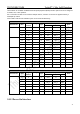
GPIO_46
115
P3
IO
Fast boot select bit 9 (configure external boot
device); Configurable I/O
GPIO_79
E3
P3
IO
Fast boot select bit 10 (configure external
boot device); Configurable I/O
GPIO_78
E2
P3
IO
Fast boot select bit 11 (configure external
boot device); Configurable I/O
GPIO_47
120
P3
IO
Fast boot select bit 12 (configure external
boot device); Configurable I/O
GPIO_50
117
P3
IO
Fast boot select bit 13 (configure external
boot device); Configurable I/O
GPIO_80
E4
P3
IO
Fast boot select bit 14 (configure external
boot device); Configurable I/O
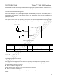
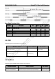
3.3.15 Debug UART Interface
This is interface dedicate for debug.
Debug UART Pins
Pin Name
PIN Location
Voltage
Type
Description
Notes
GPIO_17
C26
P3
DO
MSM_UART_TX
GPIO_18
D26
P3
DI
MSM_UART_RX
Table 3-16 Debug UART interface definition
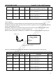
3.3.16 PWM
The GPIO_03 can be configured to send the output of the PWM waveform through special functions that can
control the external current drivers for LED.
PWM Pin
Pin Name
PIN Location
Voltage
Type
Description
Notes
PM_GPIO_03
D4
Software configurable:
VIN0 = 3.6V (Nominal)
VIN1 = 1.8V
DO
Configurable GPIO
Table 3-17 PWM definition
3.3.17 Sleep Clock
The sleep-clock output from PMS405, and it is generated following ways:
■ Calibrated low-frequency RC oscillator, periodically uses the 38.4 MHz XO signal for calibration, achieving
accuracy suitable for the real-time clock.