
Data Sheet


THUNDERCOMM TurboX™ C40x SoM Datasheet
32
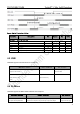
Reset Pin
Pin Name
PIN Location
Voltage
Type
Description
Notes
KPDPWR_N
C6
V_INT
DI
Long press to reset PMIC. (active low)
Table 3-14 Reset interface definition
These reset triggers each have individual debounce and delay timers. Their default values are 10.256
seconds for stage 1 and 2 seconds for stage 2, respectively, and they share the stage 3 reset timer. Stage 1
and stage 2 timers run in series, and stage 3 timer runs independently (parallel) of stage 1 and stage 2 timers.
If the stage 3 timer is set to a lower value than that of stage 1 and stage 2 combined, then the stage 3 reset
happens first. The stage 3 default values is 128 seconds.
3.3.14 Boot Configuration Interface
There are two types of boot-related fuses:
■ Fast boot fuse is used by the boot code to determine which memory device should the chip use for boot.
■ Secure boot fuse where device encryption is used to ensure that the code running on QCS40x is from a
trusted source.
Configure fuses or BOOT_CONFIG pins.
■ BOOT_CONFIG pins provide flexibility during product development.
■ Fuses should be blown for production devices.
■ BOOT_CONFIG [3:1] is MSB-aligned with Fast_Boot [2:0].
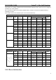
Boot Configurations:
BOOT_CONFIG[3:1]
Boot Options
Notes
0b000
Try SDC1 --> SDC2 --> USB2.0
default
0b001
Try SDC2 --> SDC1
0b010
Try SDC1
0b011
Try USB2.0
Default boot configuration (0b000) is eMMC on SDC1.
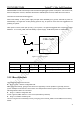
Special boot-related GPIO features:
■ They are sensed for boot-purposes during IC reset (during fuse sense).
■ After bootup, use them for normal GPIO functions.
■ Do not have pull-ups on GPIO_55, GPIO_56, GPIO_57, and GPIO_49 prior to blowing FAST_BOOT fuses.
The boot configuration function of the preceding GPIOs is sampled at the rising edge of RESOUT_N
reassertion.
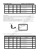
Boot Configuration Interface
Pin Name
PIN Location
Voltage
Type
Description
Notes
GPIO_45
114
P3
IO
Forced USB boot; Configurable I/O