TP610C USER'S MANUAL TP610C 1 THUNDER POWER RC
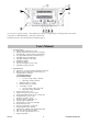
1: LCD screen 2: Upgrade connector 3: BL-2 (balance tap) connector 4: Charge Output 5: Enter/Stop button 6: INC button 7: DEC button 8: SEL/MODE button 9: Data port 10: Power input Note:Please refer BL-2 connection diagram for TP batteries (page 9). User's Manual 1. System Features a) b) c) d) e) f) g) h) i) j) 2. Highly efficient Digital power system Specially designed for safe Lipo and A123 charging. Individual cell over charge protect (when balancing). 25 programmable memories for each battery type.
Cautions!!! 3. a) b) c) d) e) f) g) h) i) j) k) Do not charge in a vehicle Use a high quality power supply for input power source Do not charge in direct sun light Do not charge when ambient temperature is extremely high Use and store in a dry environment Charge in an isolated area away from flammable objects Do not attempt to charge when battery pack is hot Do not charge unattended Do not use automotive battery chargers for power source Make sure to check battery chemistry settings before charging.
LiPo /A123 Discharge cutoff voltage settings (Lipo/A123 mode only) Press[INC] or [DEC] to change settings. LiPo/A 123 Dchg Option CUT OFF: 3.45V LiPo or A123 initial charge timer: If a pack is over discharged, the charge current will be minimized until the pack voltage achieves a minimum safe starting level. Press [INC] or [DEC] to change settings. LiPo/A 123 Init Charge TimeOut: 10 MIN PB Charge TOPOFF 2.45V /CELL PB (SLA) TOPOFF voltage setting (default 2.
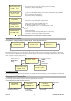
Cell count reconfirm message The following display is informing you that the pack is at an unsafe voltage level. Double check the pack cell count again. If the cell count is correct, press [INC] to continue charge. Cell count Error May Cause Fire XX Cell selected Charge If Correct Lipoly/A123 battery pack charge sequences( see Fig-2) Fig-2 Start charge Lipoly charging sequence is shown below. Each step is specially designed for the safe lipoy charge algorithm. 1. Checking 20.
Battery recovery mode for Lipo and A123 When a battery pack is extremely over discharged, the charger will refuse to initiate. At this time, you can increase the voltage to normal by using recovery mode. We strongly recommend this mode for experienced users only. When the LCD screen displays as below and the charge begins, press the [INC] key to activate a recovery charge mode. It is timed for 1 minute. Li 20.000V 0.00A Voltage Low Recover [+] Press [INC] key to recover low pack voltage.
PB (SLA) Charge As [Sel] flashes, press the [INC] or [DEC] buttons to select a memory position. Quickly press the [ENT] key, the memory slot position will flash. Select a desi red current and voltage by pressing the [INC] or [DEC]. Press the [ENT] key for 2 seconds to initiate charging. PB Charge [Sel] 12V Pack C= 5.0A Nicd/NiMH cycler Quickly press the [ENT] button. The charge, discharge current and number of cycles will flash. Press [INC] or [DEC] to change values while the screen flashes.
Definitions 1. 2. 3. 4. 5. 6. 7. 1C charge : Current of 1 times the rated capacity of the battery. Example: 4000mAh Pack = 4A charge 2s: 2 CELLS in series connection. Example: a 2s pack has the voltage of 2 cells (3.7 X 2 = 7.4V). CC Charge: Constant current charge. CV charge: Constant voltage charge. CH: Higher cell voltage. CL: Lower cell voltage Imbalance voltage: Maximum voltage differential between any cells within a pack. Error Message and symptoms 1.
Example: TP 4 / 5 cell lipo pack connection diagram BL-2 PCB BL-2 connector PCB Use both connectors for 6s TP pack NOTE: 2-3-4-5-6s CONNECTORS ARE FOR SOME CHINESE MADE PACKS ** TP Pack connections ** 2/3s Pack: use 2-3s connector 4/5s Pack: use 4-5s connector 6s pack: use 2-3s and 6s connectors TP610C 9 THUNDER POWER RC
Thunder Power RC 4880 W University Ave.