
User Manual
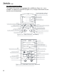

6.2 Electrical Drawings (for use with Yaskawa Drive)
Before installation and or servicing electricity to the VFD, refer to the Yaskawa
user manual supplied with the Pressurizer-VS for all safety warnings and cautions.
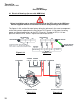
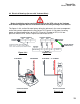
The figures in this section illustrate factory wiring for reference in the event a component
or the wiring needs replaced on the Pressurizer-VS. Figure 6-2-1 illustrates incoming
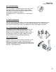
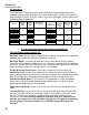
power and ground connections to the VFD. Figure 6-2-2 motor to VFD, 6-2-3 low-
pressure switch to VFD, and 6-2-4 pressure transmitter to VFD.
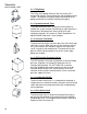
YASKAWA TERMINAL
VOLTAGE
MOTOR
YASKAWA
GROUND
YASKAWA
GROUND
MOTOR GROUND
(CONDUIT BOX)
YASKAWA TERMINAL
INCOMING POWER AND GROUND
NOTE: USE L1, L2, AND L3 FOR 3 PHASE.
USE L1 AND L2 FOR 208-240 SINGLE PHASE.
R/L1 S/L2
TL3
U/T1 V/T2 W/T3
1
3
2
1‐73‐92‐8
460V3PH
208‐230V3PH
4‐7/5‐8/6‐9
4‐5‐6
Figure 6-2-1 Figure 6-2-2
Pressure TransmitterLow-Suction Switch
A2 ON DRIVE V+ ON DRIVES3 ON DRIVE
12
34
00HN7
ZERO
R11
SPAN
ZERO
MENU
LED
CONN
SN ON DRIVE
Figure 6-2-3 Figure 6-2-4
Thrush Co.
Manual #9636-1400
13