
Owner Manual


å
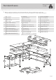
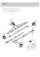
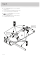
Flip the DRAWER UPRIGHTS over.
å
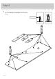
Separate the EXTENSION SLIDES (GG) from the EXTENSION RAILS (FF) as shown in the upper diagram. Be
prepared, the parts are greasy.
å
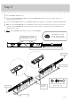
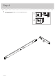
Fasten the EXTENSION RAILS (FF) to the DRAWER UPRIGHTS (P and Q). Use six BLACK 1/2” PAN HEAD SCREWS (19).
å
NOTE: For each EXTENSION RAIL, turn a SCREW into the hole shown in the enlarged diagram. Then, slide the inner
cartridge of the EXTENSION RAIL in to fi nd the other two holes that lines up with the hole in the UPRIGHT. Turn a
SCREW into these holes.
å
NOTE: The EXTENSION SLIDES will be used later for the DRAWERS.
Step 3
Use these holes to fasten the
EXTENSION RAIL to the part.
Push the black lever down and pull the SLIDE from the RAIL.
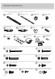
BLACK 1/2" PAN HEAD SCREW
(6 used in this step)
19
GG
FF
FF
FF
P
Q
Page 7
Just think. The sooner
you do this, the sooner
you do something else.
Finished edge
Open end
Surface without
HIDDEN CAMS
Surface without
HIDDEN CAMS
Open end
Finished edge
Edge with
small holes