
Installation & Assembly
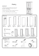

Assembly Instructions 4/7
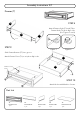
Lock
Lock
Adjustable Pin
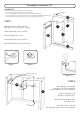
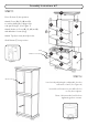
STEP 6
Attach Rail (N) to Side Panel (G),
then flip Lock.
Slide Back Panel (K) into position.
Attach Upright (L) to unit.
Slide Back Panel (K) into position.
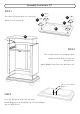
Attach Rail (N) to unit,
then flip Lock.
Attach Side Panel (H) to unit,
then flip Locks.
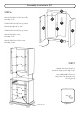
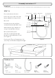
STEP 7
Attach unit from Step 5 to
unit from Step 4, then flip Locks.
Insert Adjustable Pins into
side panels at desired level.
(See Figure 4)
Figure 4
N
N
K
K
L
G
H