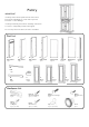
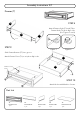
Pantry IMPORTANT Carefully remove all the parts from the carton and place them individually on a soft cloth to prevent scratches or other damage. Carefully and strictly follow these assembly instructions to ensure a completed product as designed. Do not use power tools above 8 volts to assemble. Part List B. Side Panel 1 pc. C. Side Panel 1 pc. G. Side Panel 1 pc. H. Side Panel 1 pc. I. Back Panel 2 pcs. J. Upright 1 pc. K. Back Panel 2 pcs. L. Upright 1 pc. M. Rail 1 pc. N. Rail 4 pcs. F.
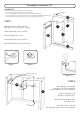
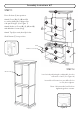
Assembly Instructions 2/7 IMPORTANT Use a soft cloth between these parts and the floor. Do not use power tools above 8 volts to assemble. Do not tighten all the screws until each part is properly assembled. The unit must be level to work properly. Use the included adjustable levelers to level. Keep Hex Wrench as the bolts may need to be tightened in the future. Lock N STEP 1 I I Attach Rail (N) to Side Panel (B), then flip Lock. (See Figures 1 and 2) Slide Back Panel (I) into position.
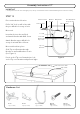
Assembly Instructions 3/7 STEP 3 F Place Base (E) upside down on a soft cloth. F F Attach Feet (F) to Base (E). F E D Lock STEP 4 Turn over base unit to its’ upright position. Attach unit from Step 2 to base unit, then flip Locks. Attach Middle Panel (D) to unit, then flip Locks. Wood Screw for Magnet Magnet STEP 5 Place Top (A) upside down on a soft cloth. Attach Magnet to Top (A) with Wood Screws for Magnet into pre-drilled holes.
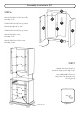
Assembly Instructions 4/7 N STEP 6 Attach Rail (N) to Side Panel (G), then flip Lock. K K Slide Back Panel (K) into position. Attach Upright (L) to unit. G L H Slide Back Panel (K) into position. Attach Rail (N) to unit, then flip Lock. N Attach Side Panel (H) to unit, then flip Locks. Lock STEP 7 Attach unit from Step 5 to unit from Step 4, then flip Locks. Insert Adjustable Pins into side panels at desired level.
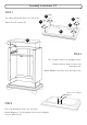
Assembly Instructions 5/7 Drawer (T) STEP 8 T4 Attach Drawer Sides (T3) and (T4) to Drawer Back (T2), then flip Locks. (See Figures 5 and 6) T2 T3 Lock STEP 9 Figure 5 Figure 6 Slide Drawer Bottom (T5) into groove. Attach Drawer Front (T1) to unit, then flip Locks. T1 T5 Machine Screw Knob Lock STEP 10 Attach Knobs with Machine Screws. Part List T1. Drawer Front 1 pc. T2. Drawer Back 1 pc. T3. Drawer Side 1 pc. T4. Drawer Side 1 pc. T5. Drawer Bottom 1 pc.
Assembly Instructions 6/7 STEP 11 A Place Shelves (S) into position. Attach Doors (O), (P), (Q) and (R) to unit by sliding door hinges into side panel hinges. (See Figure 7) Q R S Attach Knobs to Doors (O), (P), (Q) and (R) with Machine Screws (long). Attach Top (A) to unit, then flip Locks. S Slide Drawer (T) into position. T Knob Machine Screw (long) O P S Figure 7 S Wood Screw STEP 12 Level unit by adjusting the adjustable levelers on bottom of unit.
Assembly Instructions 7/7 IMPORTANT To help reduce the risk of the unit tipping over, the Tip-over Restraint must be installed following these instructions exactly. STEP 13 Anchor in wall Place unit at desired location. Drill a 3/8” hole in wall in-line with the pre-drilled hole at top of unit. Bracket on wall Pre-drilled hole at top of unit Wall Screw 3/8” wall hole Wood Screw Move unit. Tie end Insert Anchor into the wall hole and attach Bracket with Wall Screw.