ENTRYWAY STORAGE CABINET 1/18
DO NOT RETURN FOR REPLACEMENT PARTS OR OTHER INQUIRIES PLEASE CONTACT US.
IMPORTANT : Please read this manual carefully before beginning assembly of this product. Keep this manual for future reference. SAFETY INFORMATION Identify all the parts and hardware. Do not discard of the packaging until you have checked that you have all of the parts and hardware required. Hardware package may have spare parts. WARNING: This item contains small parts which can be swallowed by children and pets. Keep children and pets away during assembly.
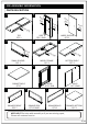
PRE-ASSEMBLY INFORMATION PARTS DESCRIPTION A B C Ba ck Sid e Ba ck Sid e Fro nt Sid e Fro nt S i Fro nt Sid e de TOP QTY 1 SIDE QTY 1 PAIR D LARGE DIVIDER QTY 1 E F Fro nt Sid e Fro Fro nt S i SMALL DIVIDER QTY 1 H BOTTOM SHELF QTY 1 I BACK QTY 1 PAIR DOOR QTY 1 PAIR CABINET SHELF QTY 2 K DRAWER FRONT QTY 2 de MIDDLE FRAME QTY 1 G J nt S i de L DRAWER SIDE QTY 2 PAIRS M DRAWER BACK QTY 2 DRAWER BOTTOM QTY 2 NEED HELP? For help with assembly or if you are missing a part
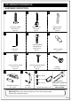
PRE-ASSEMBLY INFORMATION HARDWARE DESCRIPTION 2 1 3 ALLEN KEY SCREW M6 X 30 mm QTY 26 4 5 6 PHILLIPS SCREW ROUND HEAD M4 X 15 mm QTY 21 ALLEN KEY QTY 1 7 8 PHILLIPS SHORT SCREW M3 X 12 mm QTY 12 10 SHELF SUPPORT QTY 12 9 PHILLIPS MEDIUM SCREW M3 X 15 mm QTY 8 11 MAGNET and PLATE QTY 2 SETS WOOD DOWEL 8 X 30 mm QTY 16 CAM LOCK PIN CAM LOCK QTY 16 HANDLE QTY 2 SETS 12 HANDLE QTY 2 SETS a. M4 x 25mm b. M4 x 15mm Required c.
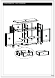
COMPONENTS – KEY DIAGRAM 6/18
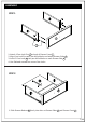
ASSEMBLY STEP 1 1. Attach 4 Cam Lock Pins 2 to back of Drawer Front J . 2. Align Cam Lock Pins with pre-drilled holes and attach Drawer Sides K . 3. Insert 2 Cam Locks 2 into pre-drilled holes on each Drawer Side K . 4. Use flathead screwdriver secure Cam Locks. STEP 2 1. Slide Drawer Bottom M firmly into slots on Drawer Sides K and Drawer Front J .
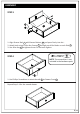
ASSEMBLY STEP 3 1. Align Drawer Back L with Drawer Bottom M and press firmly into slot . 2. Attach back using 2 Allen Key Screws 1 through pre-drilled holes on each Side K . 3. Use Allen Key 4 to tighten screws. Do not over-tighten. STEP 4 NOTE: The screwdriver is not included in the hardware pack. 1. Use Phillips Screwdriver to attach Handle 9 to Drawer Front J . Repeat Step 1-4 for the second drawer.
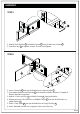
ASSEMBLY STEP 5 1. Attach Small Divider D to Middle Frame E using 2 Allen Key Screws 1 . 2. Use Allen Key 4 to tighten screws. Do not over-tighten. STEP 6 1. Insert 2 Dowels 3 into pre-drilled holes on Large Divider C . 2. Use rubber mallet to tap Dowels 3 into bottom of holes securely. ½ length of Dowels should be exposed. 3. Attach 2 Cam Lock Pins 2 to Middle Frame E into guide holes. 4. Align and insert Cam Lock Pins on Middle Frame E into pre-drilled holes on Large Divider C . 5.
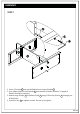
ASSEMBLY STEP 7 1. Insert 2 Dowels 3 into pre-drilled holes on Large Divider C . 2. Use rubber mallet to tap Dowels 3 into bottom of holes securely. ½ length of Dowels should be exposed. 3. Attach Large Divider C to Bottom Shelf F using 3 Allen Key Screws 1 through predrilled holes. 4. Use Allen Key 4 to tighten screws. Do not over-tighten.
ASSEMBLY STEP 8 1. Insert 4 Dowels 3 into pre-drilled holes on each Side B . 2. Use rubber mallet to tap Dowels 3 into bottom of holes securely. ½ length of Dowels should be exposed. 3. Attach 3 Cam Lock Pins 2 to each Side B into guide holes. 4. Align and insert Cam Lock Pins on Sides B into pre-drilled holes on Bottom Shelf F . 5. Place 6 Cam Locks 2 into pre-drilled holes on Bottom Shelf F 6. Use a flathead screwdriver to tighten Cam Locks into Pins. 7.
ASSEMBLY STEP 9 1. Insert 2 Dowels 3 into top corners of each Side B . 2. Use rubber mallet to tap Dowels 3 into bottom of holes securely. ½ length of Dowels should be exposed. 3. Align pre-drilled holes bottom corners of Top A with Dowels 3 in Sides B . 4. Attach Top A to Sides B and Small Divider D using 9 Allen Key Screws 1 . 5. Use Allen Key 4 to tighten screws. Do not over-tighten. STEP 10 NOTE: The screwdriver is not included in the hardware pack. 1.
ASSEMBLY STEP 11 NOTE: The screwdriver is not included in the hardware pack. 1. Attach Hings on Doors H to Sides B using Phillips Screws 7 into pre-drilled guide holes. 2. Attach Magnet Plates 10 to bottom corner of Doors H using Phillips Screws 8 . into guide holes on Doors H . 3. Attach Magnet 10 to Bottom Shelf F using Phillips Screws 8 into guide holes on Bottom Shelf F . 4. Use Phillips screwdriver attach Handles 11 to Doors H .
ASSEMBLY STEP 12 1. Use 4 Shelf Supports 6 for each Shelf Cabinet G in desired location. 2. 2 Shelf Supports 6 may be used on back top of each Shelf Cabinets G as a tipping restraint. 3. Insert assembled drawers into drawer glides on assembled cabinet.
ASSEMBLY When you determine the location for your unit, install the Furniture Tipping Restraint. Carefully follow the instructions on the package. STEP 13 NOTE: The screwdriver is not included in the hardware pack. STEP 14 STEPS 13 & 14 1. To attach Tipping Restraint 12 , fllow instructions on Tipping Restraint package.
WARRANTY Thank you for purchasing our product. These products have been made to demanding, high-quality standardsand are guaranteed for domestic use against manufacturing faults for a period of12 months from the date of purchase. This warranty does not affect yourstatutory rights. In case of any malfunction of your product (failure, missing parts, etc.) please contact us at our toll free service line. We reserve the right to repair or replace the defective product, at its discretion.