
Specification Sheet

STEP 1:
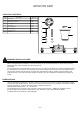
a Screw the Mounting Screws into the Crossbar place the
Lock Washers over the Mounting Screws and thread the
Hex Nuts onto the Mounting Screws as shown Secure the
position of the Mounting Screws by tightening the Hex Nuts
against the Crossbar
b Secure the Crossbar to the Outlet Box with Outlet Box
Screws
. ,
.
.
.
.
Outlet Box
Crossbar
Mounting Screw
Hex Nut
Outlet Box Screw
Lock Washer
INSTALLATION INSTRUCTIONS
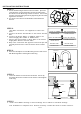
WHITE OR RIBBED
BLACK OR RED WIRE( )
FROM HOUSE
GROUND WIRE GROUND WIRE
FROM HOUSE FROM FIXTURE
WHITE OR RIBBED
FROM FIXTURE
FROM HOUSE
FROM FIXTURE
BLACK OR SMOOTH
STEP 2:
* ( )
.
.
. ( )
( )
. ( )
( ).
.
.
Use Wire Connectors not supplied to connect the
wires
a Connect the House Ground Wire to the Fixture Ground
Wire.
b Connect the House White or Ribbed Wire to the
Fixture Supply Wire White or Ribbed Side .
c Connect the House Black or Red Wire to the Fixture
Supply Wire Black or Smooth Side
d Wrap each connection with approved electrical tape and
carefully stuff all of the connected wires into the Outlet
Box
Mounting Ball
Mounting
Screw
Backplate
STEP 3:
a Place the Backplate over the Mounting Screws and secure
with Mounting Balls. Hand tighten until snug.
.
Socket Collar
Shade
Socket
STEP 4:
a Place the Shade over the Socket As shown. Secure by
threading the Socket Collar onto the Socket. Hand tighten
until snug.
.
2 OF 2
STEP 5:
a Install correct Bulbs referring to fixture markings and or labels for maximum wattage
Your installation is completed now Restore electricity Retain this sheet for future reference
. / .
. . .