
Instruction Manual
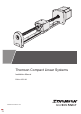

Thomson
Thomson Compact Linear Systems - Installation Manual - 2022-09 9
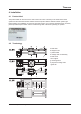
4.4.4 Mounting of CLSH and CLSV units
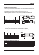
1. The mounting holes are situated in the guide rail. Their exact position and dimensions depend on the
size of the prole rail and can be found in the table below.
2. The rst mounting hole (Y) on the motor side has a positional tolerance of ± 1.0 mm from the end of
the guide rail.
2. The positional tolerance between the rest of the mounting holes (X) are 0.5 mm.
5. When bolting the unit to the surface, rst insert screws in the mounting holes and tighten lightly.
Then starting from the center of the rail moving outwards, tighten each screw to the recommended
tightening torque listed in the table in section 4.4.6.
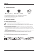
4.4.5 Mounting of CLSR units
1. The mounting holes are situated in the end supports (Z). Their exact position and dimensions depend
on the size of the round rail and motor size and can be found in the table below.
2. When bolting the unit to the surface, rst insert screws in the mounting holes and tighten lightly.
Then tighten each screw to the recommended tightening torque listed in the table in section 4.4.6.
4.4.6 Recommended bolt tightening torque table
Recommended bolt tightening torque [Nm]
Class
Size
M2.5 M4 M5 M6 M8 M10 M12 M14 M16
8.8 0.7 2.8 5.7 9.5 23 46 80 129 198
12.9 1.2 4.6 9.5 16 39 77 135 215 330
CLSH/CLSV mounting holes
Style Size X [mm] Y [mm]
CLSH 15F 60 20
CLSV 9A 20 7.5
CLSV 12A 25 10
CLSV 15A 40 15
CLSV 15F 60 20
CLSR mounting holes
Motor Size Bearings P [mm] R [mm] X [mm] Y [mm]
NEMA 23 R08 29.0 60.0 17 6.35
NEMA23 R06 20.5 60.0 17 6.35
NEMA 17 R08 29.0 64.75 17 6.35
NEMA 17 R06 20.5 60.5 17 6.35