
Instruction Manual

Thomson
Thomson Compact Linear Systems - Installation Manual - 2022-0910
4.5 Electrical installation
4.5.1 General notes
• Make sure the leads/cables leading to the motor can handle the maximum motor current.
• Do not exceed the peak current of the motor. Peak current is 1.41 × RMS current.
• An emergency stop is recommended to reduce the chance of a crushing hazard.
• Never work on the linear system or the wiring with the power switched on.
4.5.2 Electrical connections
The linear system motor is always supplied with ying lead wires that are attached to the stepper motor.
These lead wires are used to connect to the stepper motor and drive the carriage. Depending on the
conguration, motors have various wire gauge sizes. The standard gauges are outlined in the table below.
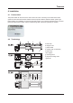
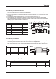
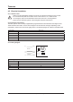
4.5.3 Wiring diagram
Conguration Wire gauge
NEMA14Axx 26 AWG
NEMA17Axx 26 AWG
NEMA17Bxx 26 AWG
NEMA23Axx 22 AWG
NEMA23Bxx 22 AWG
Motor wiring
Lead color Motor phase
Blue A -
Red A +
Black B -
Green B+
M
B +
Phase A
Phase B
B -
A + Red
Blue
Green
Black
A -