
User's Manual Part 5

Digital Liquid Cooled UHF
TV Equipment
Use of commands and description of indicators
9932 V2
45321648.01 108 B E
Checked
190 / 192
Numéro / Number Doc. Rev. Lan
g
u.
27/06/2006
Pa
g
e
Information contained is this document is confidential, is THOMSON property and cannot be disclosed in whatever form without prior written authorization of THOMSON.
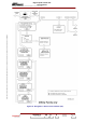
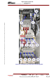
2.6. Power supply unit
2.6.1. Using the commands
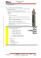
The amplifier power supplies are fed via a switch
fuse isolator for protection of the power supply,
accessible to the operator on the front panel.
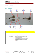
2.6.2. Indicator lamps and message
displays
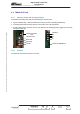
A green LED on the upper panel indicates the
status of the power supply as follows :
♦ when lit up it indicates that there is an output
DC voltage and that the power supply is in
operation,
Green Led
output voltage
present
06/086(e)
♦ when extinguished it indicates that there is no output DC voltage and that the power supply is shut
down or faulty.
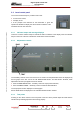
Note :
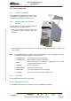
The «POWER SUPPLY» window which can be displayed on the PCL displays the status
conditions for the power supplies in a bay as follows :
♦ POWERED OFF
: power supply shut down but fault-free,
♦ POWERED ON
: power supply in operation and fault-free,
♦ FAULT
: mains input failure; this indication is independent of the power
supply operational status (on or off),
♦ MISSING
: power supply absent,
♦ BREAKER OFF
: fused isolator open circuited,
♦ MAINS FAULT
: one of the mains fuses F2 to F4 has failed,
♦ UNKNOW
: internal power supply fault in the multiplex card.
2.6.3. Test points
The amplifier power supply has no test points.
2.6.4. Adjustment controls
The amplifier power supply has no adjustment controls available to the operator.