
User's Manual Part 5

Digital Liquid Cooled UHF
TV Equipment
Use of commands and description of indicators
9932 V2
45321648.01 108 B E
Checked
188 / 192
Numéro / Number Doc. Rev. Lan
g
u.
27/06/2006
Pa
g
e
Information contained is this document is confidential, is THOMSON property and cannot be disclosed in whatever form without prior written authorization of THOMSON.
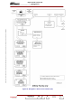
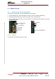
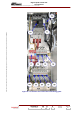
2.5. RF amplifier unit
2.5.1. Indicator lamps and message displays
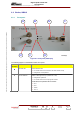
♦ A LED indicator on the front panel of the amplifier card indicates the status
of the transmitter as follows :
• LED extinguished : voltage supply has failed or is ≤ 24V,
• green LED : amplifier voltage supply is present and it is working
satisfactorily,
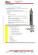
• red LED :
- transistor failure as follows :
I < 2.4 A for a group of 4 power transistors with polarisation (P input >
-4dBm)
- overdrive (over current or power protection system activated and fault
stored : 45 A for 4 double transistors),
- P input > -4 to -3dBm and P output <250W
- SWR protection system activated and fault stored (≥ 2 ),
- thermal protection system activated and fault stored (air input
temperature ≥ 60°C),
• orange LED : internal power supply absent in the protection system card.
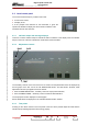
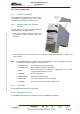
NOTE:
The PCL «AMPLIFIERS» window displays the status
conditions of a power amplifier as follows :
• transistor current values:
- T1 : amplifier modules 1 and 2,
- T2 : amplifier modules 3 and 4,
- T3 : amplifier modules 5 and 6,
- T4 : amplifier modules 7 and 8,
- T5 : transistors in class AB drive amplifier,
- T6 : transistors in class A preamplifier,
• ON,
• general fault,
• SWR fault,
• overdrive fault,
• internal temperature fault,
• presence/absence.
T1
T2
T3
T4
T5T6