
User's Manual Part 4

Digital Liquid Cooled UHF
TV Equipment
Use of commands and description of indicators
Information contained is this document is confidential, is THOMSON property and cannot be disclosed in whatever form without prior written authorization of THOMSON.
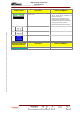
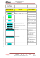
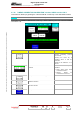
2.1.40. "LOCAL/IMAGE REJECT" window, SIRIUS version ONLY
This window i ed up by p keys in the "SETTINGS" window. s call ressing the "REJECT" control
NOTE : This window is available in SIRIUS version only.
This window is only available in maintenance mode.
CONTROL KEYS FUNCTIONS DISPLAY/COMMENTS
Decrements the adjustment value of the
“OFFSET I” by step of 1 or by step of 10.
Displays the adjustment value of the
“OFFSET I”
Increments the adjustment value of the
“OFFSET I” by step of 1 or by step of 10.
Decrements the adjustment value of the
“OFFSET Q” by step of 1 or by step of 10.
Displays the adjustment value of the
“OFFSET Q”
Increments the adjustment value of the
“OFFSET Q” by step of 1 or by step of 10.
Allows to adjust the I & Q/RF modulator
(Local Oscilator Rejection)
Obtain the maximum rejection of the local
frequency (<35dB).
The adjustments are directly applied to the
basic transmitter.
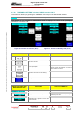
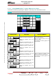
Decrements the adjustment value of the
GAIN by step of 1 or by step of 10.
Displays the adjustment value of the GAIN.
Increments the adjustment value of the
GAIN by step of 1 or by step of 10.
Decrements the adjustment value of the
PHASE by step of 1 or by step of 10.
Displays the adjustment value of the
PHASE.
Allows to adjust the rejection of the
unwanted lateral band (image Rejection)
The adjustments are directly applied to the
basic transmitter.
9932 V2
45321648.01 108 B E
Checked
142 / 192
Numéro / Number Doc. Rev. Lan
g
u.
27/06/2006
Pa
g
e