
User's Manual Part 4

Digital Liquid Cooled UHF
TV Equipment
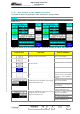
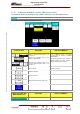
Use of commands and description of indicators
Information contained is this document is confidential, is THOMSON property and cannot be disclosed in whatever form without prior written authorization of THOMSON.
(*)
Calls up data from the other exciter.
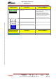
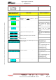
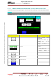
INDICATOR LAMPS AND
MESSAGE DISPLAYS
FUNCTIONS DISPLAY/COMMENTS
Gives the window name.
Displays, which gain control mode (MANUAL or
AUTOMATIC) is currently
picked up by the
transmitter
GAIN MANUAL / GAIN AUTO
Indicates the status of the AGC loop.
AGC OK / AGC FAULT
FAULT: The AGC voltage is out of
the operation range:+-2dB (0,5V to
2,5V) regarding AGC reference.
It’s displays in “AGC SETTING”
screen.
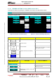
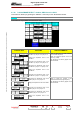
Displays which gain control mode is selected AUTO / MANUAL
GAIN””
ted or
cleared.
Flashes until the “
command is either valida
Displays the transmitted RF power value This value is expressed in a
percentage of the calibrated power
value.
Displays the current value for the Auto Gain C
(AGC) loop that is picked up by the transmitter.
ontrol
Displays the reference value in Auto Gain C
(AGC) that is used.
ontrol
Indicates the level of the feedback signal for Linear
Correction (Ripple)
Green indication: OK
used:
to +2dBm
Red indication: FAULT
The RF feedback level is out of the
range:
FLO or COFDM modulator used:
typical –10dBm to 0dBm
8VSB modulator
typical –15dBm
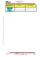
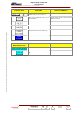
Indicates the level of the feedback signal for Linear Green indication: OK
modulator used:
typical –10dBm to 0dBm
8VSB modulator used:
Correction (Shoulder)
Red indication: FAULT
The RF feedback level is out of the
range:
FLO or COFDM
typical –15dBm to +2dBm
(*)
C A / EXC B Indicates which exciter data are displayed. EX
(*) : Only Dual-Drive v rsion.
e
9932 V2
45321648.01 108 B E
Checked
141 / 192
Numéro / Number Doc. Rev. Lan
g
u.
27/06/2006
Pa
g
e