
User's Manual Part 3

Digital Liquid Cooled UHF
TV Equipment
Use of commands and description of indicators
Information contained is this document is confidential, is THOMSON property and cannot be disclosed in whatever form without prior written authorization of THOMSON.
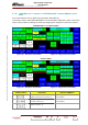
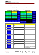
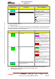
CONTROL KEYS FUNCTIONS DISPLAY/COMMENTS
(*)
Indicates the exciter selected. EXC A / EXC B
Fla
is eithe
shes until the "EXCITER SEL" command
r validated or cleared.
(*)
Indicates the exciter changeover mode. MAN /
Flashe H OVER" command is
either validated or cleared.
MAN
AUTO
s until the "C
Manual) : only when operator gives a
nd.
(
comma
AUTO
: when the selected exciter is faulty.
A manual changeover can be commanded
reg
be
ardless of which changeover mode has
en selected.
(*) : Only in Double Drive Version
(**) : Single Drive Version
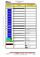
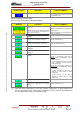
(1) : A fault-free status is displayed in normal video (on black ba
case of colour tactile screen). A faulty status is displayed in reverse vid
red background in case of colour tactile screen).
ckground or green background in
eo (on white background or on
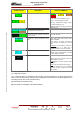
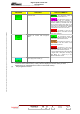
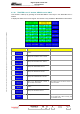
MESSAGES FUNCTIONS DISPLAY/COMMENTS
Indicates the exciter changeover status in
automatic mode.
: the changeover system is
y for an automatic switch ovread er.
: the changeover system is no
longer available and it is necessary to
change the exciter selected or to carry out a
transmitter "RESET" (in this latter case, care
must be taken because fault data for all
faults which have disappeared will be erased
together with their consequences; similarly
for all selections carried out on the PCL).
: an attempt to carry out an
automatic changeover has failed and the
buzzer will be triggered.
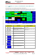
Indicates the
status.
external GPS changeover
: the changeover system is
ready for an automatic switch over. The free
contact of the external GPS is closed.
: the changeover system is no
longer available. The free contact of the
external GPS is openned.
: an attempt to carry out an
automatic changeover has failed. The free
contact of the external GPS is openned
In case of disable GPS signal the transmitter
is stopped after a delay time according to
"GPS MUTE (h) " control key in the
"MISCELLANEOUS" window.
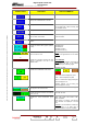
(2)
Indicates the sta
power supply of the exciter.
P. SUPPLY OK / P. SUPPLY FAULT (1) tus of the very low voltage
(3) A fault-free status is displayed in normal video (on black background or on green background
in case of colour tactile screen). A faulty status is displayed in reverse video (on white
background or on red background in case of colour tactile screen).
(4) Only Single Drive version.
9932 V2
45321648.01 108 B E
Checked
115 / 192
Numéro / Number Doc. Rev. Lan
g
u.
27/06/2006
Pa
g
e