
Operation Manual Part 3

Digital Liquid Cooled UHF
TV Equipment
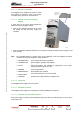
Description / Test points / Location of units
9946 V1
45321648.01 104 A E
preliminary
93 / 131
Numéro / Number Doc. Rev. Lan
g
u.
16/06/2006
Pa
g
e
Information contained is this document is confidential, is THOMSON property and cannot be disclosed in whatever form without prior written authorization of THOMSON.
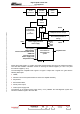
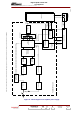
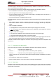
START-UP
CONTROL CIRCUIT
RECTIFIER/FILTER
(LC)
TRANSFORMER
AMPLIFIER
Amplifier presence
signals
MULTIPLEX CARD
Power supply
unit status data
On command
INTERFACE
CARD
Amplifier 1 (and 2)
extracted
Start-up command
(shut down)
U regul.
CONTACTS
PRESENT
DC power
supply output
OUTPUT VOLTAGE
REGULATION
DC/DC
CONVERTERS
MAINS LIMITATION/
PROTECTION/
SURVEILLANCE
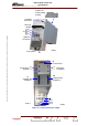
MAINS FILTER
(FL1)
BOOST
INDUCTOR
TRANSFORMER RECTIFIER/FILTER
Mains
S1
POWER SUPPLY UNIT
24V DC
06/092 (e)
RECTIFIER (CR1)
BOOST
INDUCTOR
POWER FACTOR
CORRECTION
(PFC CARD)
Output voltage
value
Amplifier 1 (and 2)
present
F1
Figure 21 : Block diagram of an amplifier power supply