
Operation Manual Part 3

Digital Liquid Cooled UHF
TV Equipment
Description / Test points / Location of units
9946 V1
45321648.01 104 A E
preliminary
92 / 131
Numéro / Number Doc. Rev. Lan
g
u.
16/06/2006
Pa
g
e
Information contained is this document is confidential, is THOMSON property and cannot be disclosed in whatever form without prior written authorization of THOMSON.
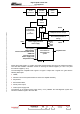
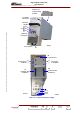
3.11.1.1. Operational description
The input three phase mains supply passes through protection fuses F1 to F3, and then passes
successively through the following :
♦ filter unit (FL1) for parasite elimination,
♦ circuit for current limitation and mains protection and surveillance devices.
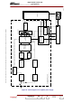
The mains supply is then rectified by a diode bridge rectifier (CR1) followed by a PFC circuit (boost
inductance + PFC card).
The resulting DC voltages are fed to a PFC card which improves the power factor of the incoming
mains by :
♦ arranging that incoming current is totally sinusoidal,
♦ reducing the harmonics.
The PFC card has two choppers separated by a phase delay of 90°. The currents are added and fed
to two DC/DC converters in an H bridge configuration and installed on the control card.
A pulse width modulating circuit which is controlled by the output voltage is used to control the
waveform pulse width. This is the basic mechanism for controlling the output voltage.
This modulating circuit which is synchronised to the PFC card uses control circuits to control the
operation of the H bridges so that the waveform is shaped properly and the chopping action is
synchronised.
The pulse width modulation circuit is fed by an auxiliary 24 V DC fed from a step-down transformer
followed by rectification and filtering.
Each DC/DC converter feeds a transformer primary winding. The unidirectional voltage cycles from the
secondary winding go through a further push-pull rectifying circuit followed by an «LC» filtering circuit
and the resulting voltage is then fed to the power supply module output.
Each amplifier power supply has an output interface card containing logic circuits which :
♦ generate power supply start-up and shut-down commands (see § «Surveillance devices»),
♦ control the output voltage and adjust it to the set value. The set value is encoded into a 3 bit word
which is sent by the multiplex card and can be set by using internal switches in the multiplex card
(this only applies to the Ultimate range of UHF transmitters).
Note :
On high power transmitters all command and status data exchanged between the multiplex
card and the RF power amplifiers pass through the amplifier power supplies.