
Operation Manual Part 3

Digital Liquid Cooled UHF
TV Equipment
Internal and external connections
9946 V1
45321648.01 104 A E
preliminary
120 / 131
Numéro / Number Doc. Rev. Lan
g
u.
16/06/2006
Pa
g
e
Information contained is this document is confidential, is THOMSON property and cannot be disclosed in whatever form without prior written authorization of THOMSON.
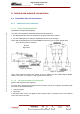
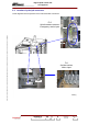
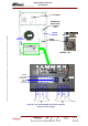
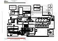
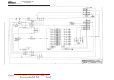
5.2. Location of principal connectors
These diagrams show the positions of the main transmitter connections.
FL2
TB
09-xx3A
(e)
09-xx2A (e)
06/115(e)
L1L2L3N
FL2
Arrivée secteur secouru
Emergency mains input
FL1
Arrivée secteur
Mains input
Capot