
Operation Manual Part 3

Digital Liquid Cooled UHF
TV Equipment
Internal and external connections
9946 V1
45321648.01 104 A E
preliminary
119 / 131
Numéro / Number Doc. Rev. Lan
g
u.
16/06/2006
Pa
g
e
Information contained is this document is confidential, is THOMSON property and cannot be disclosed in whatever form without prior written authorization of THOMSON.
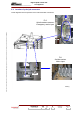
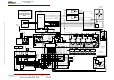
5.1.1.3. Connections for switched dc and analogue signals within the transmitter
(Refer to signal links diagram).
The transmitter sub-units have switched DC and analogue interconnections for status, display and
command data with the CPU and the multiplex card.
All data exchanges between the CPU and the transmitter sub-units pass through the digital TX
interconnection card.
All data exchanges between the CPU and the transmitter sub-units other than the exciter cards and
the user interfaces also pass through the multiplex card.
Data to and from the amplifiers pass through the amplifier power supplies.
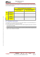
For cabinets in transmitters with power outputs greater than 4 kW, connections between the second
multiplex card and the CPU are made via the first multiplex card.
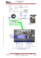
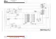
5.1.1.4. RF connections
(Refer to RF links diagram).
Coaxial cables and feeders are used for the RF signal connections between the various transmitter
sub-units.
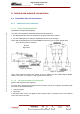
5.1.2. Connections between Central Processing Unit and user interfaces
Connections between Central Processing Unit and user interfaces
Various types of connection are used for data exchanges between the User Interfaces and the Central
Processing Unit:
♦ PCL connections (via interconnection card):
• RS 232 serial link using JBUS protocol,
• switched DC connections,
• analogue connections.
♦ serial link to a remote user interface (via interconnection card): RS 232 serial link using THALES
protocol,
♦ hard wired connections to a user interface (via interconnection card): Remote control and remote
indications conform to the IEC 864-1 standard,
♦ connection with log book terminal: RS 232 serial link.
5.1.3. Connections between cabinet and filter unit
The connections between the cabinet and the band filter consist only of RF connections for which co-
axial cables and feeders are used.