
Operation Manual Part 3

Digital Liquid Cooled UHF
TV Equipment
Internal and external connections
9946 V1
45321648.01 104 A E
preliminary
118 / 131
Numéro / Number Doc. Rev. Lan
g
u.
16/06/2006
Pa
g
e
Information contained is this document is confidential, is THOMSON property and cannot be disclosed in whatever form without prior written authorization of THOMSON.
5. Internal and external connections
5.1. Transmitter inter-unit connections
5.1.1. Cabinet inter-unit connections
5.1.1.1. Exciter Sub-assemblies links
(see RF links and signal links diagrams)
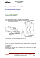
The cards of the set EMB are distributed between the following boxes:
♦ Box SIRIUS including mainly the treatment of the signal and its RF conversion,
♦ The box of Management including An amplification function for the RF signal
All the data exchanged between the subsets EMB of these boxes, pass in transit opposite back.
There are two types of connection:
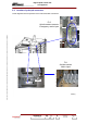
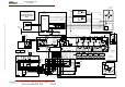
RF links
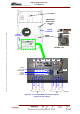
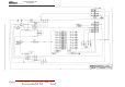
Signal links
Figure 26 : RF links
Figure 27 : Signal links
All the data exchanged between the subsets of the box SIRIUS and the outside (Signals MPEG,
10MHz, 1PPS, FdD ..), also pass in transit opposite back of this one.
5.1.1.2. Connections between CPU and exciter
(Refer to links interconnection diagrams).
The CPU card is plugged into the digital TX interconnection card and it exchanges the following with
the exciter via the serial link RS232:
♦ command signals,
♦ status data.
In the Double Drive version, the digital TX interconnection card is connected to each of the SIRIUS
rack in rear panel of the frame.