
Operation Manual Part 3


Digital Liquid Cooled UHF
TV Equipment
Description / Test points / Location of units
9946 V1
45321648.01 104 A E
preliminary
114 / 131
Numéro / Number Doc. Rev. Lan
g
u.
16/06/2006
Pa
g
e
Information contained is this document is confidential, is THOMSON property and cannot be disclosed in whatever form without prior written authorization of THOMSON.
3.14.5. Adjustments
No adjustment controls are needed on the RF coupling system.
3.14.6. Connections and data transfer
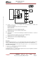
The vision channel input splitter has the following connectors:
♦ an input connector for the exciter RF output signal,
♦ output connectors for the RF signals to the inputs of the RF power amplifiers.
The F.I.C.S. combiner has the following connectors:
♦ input connectors (one per amplifier) for the RF power amplifier outputs,
♦ output connectors for the co-axial cable connections to the load circuits (one per amplifier, plus one
for the F.I.C.S. output 3 dB coupler),
♦ a feeder output which feeds the RF signal to the filter assembly.
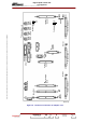
The load circuit input connectors are connected to resistor sets by co-axial cables.
3.14.7. Input power
The RF coupling system does not need any input power.
3.14.8. Cooling
The load circuits are mounted on a heat sink capable of dissipating the heat gain from the resistors.
The transmitter cooling system cools the heat sink itself. The transmitter cooling system cools the sink
itself.