
Operation Manual Part 3


Digital Liquid Cooled UHF
TV Equipment
Description / Test points / Location of units
9946 V1
45321648.01 104 A E
preliminary
112 / 131
Numéro / Number Doc. Rev. Lan
g
u.
16/06/2006
Pa
g
e
Information contained is this document is confidential, is THOMSON property and cannot be disclosed in whatever form without prior written authorization of THOMSON.
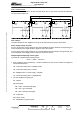
3.14. Coupling system
3.14.1. Outline
The purpose of the RF combiner is to add together the power signals from the RF power amplifiers.
An input unit splits the power signal from the exciter into signals, which are exactly matched in
amplitude and phase, and sends them to the amplifiers.
An F.I.C.S. (Full Isolated Coupling System patented by THALES) unit adds the powers signals
delivered by the amplifiers. The system has an isolating unit, which avoids mismatch problems when
one or more amplifiers fail.
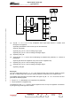
3.14.2. Architecture
The F.I.C.S. unit consists of:
♦ a stage consisting of 3 dB couplers (one coupler per amplifier),
♦ one or two load circuits,
♦ two 4 to 16 way combiners (one way per amplifier),
♦ an output 3 dB coupler.
3.14.3. Operational description
At the output of each amplifier a 3 dB coupler produces the power signals which are exactly matched
in amplitude and with an aperiodic phase difference of 90° to two distribution modules (6 inputs - 1
output). These two modules are connected to another 3 dB coupler which recombines the power
signal and delivers it to the transmitter channel output.
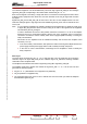
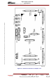
Next figure describes the basic principle of the F.I.C.S. unit:
♦ the amplifiers are connected to the inputs of the 3 dB couplers,
♦ the outputs (a) from the 3 dB couplers are connected to the distribution module (A),
♦ the outputs (b) from the 3 dB couplers (which have a phase difference 90° with the (a) outputs) are
connected to the distribution module (B),
♦ outputs (c) from the 3 dB couplers are connected to the load circuit; each input of this unit
terminates in a set of four resistors which can dissipate 850 W.
In normal operation the signals applied to the inputs of the distribution modules are exactly matched in
amplitude and phase. Hence they add together completely. The output 3 dB coupler adds the signals
and sends the combined signal to the RF output.
When not operating normally (amplitude and/or phase mismatch or amplifier failure) the signal applied
to a distribution module input has the following three components:
♦ the component transmitted to the module output,
♦ the reflected component,
♦ the component applied to the other amplifier outputs.
Because of the aperiodic phase difference of 90° between the two distribution modules, the
components, which are reflected or transmitted to the amplifiers, are recombined in the load
terminations of the 3 dB input couplers.
The components transmitted to the module output recombine at the output of the 3 dB output coupler.
Hence in all operational circumstances the system gives absolute protection to the amplifiers even in
the case of the shut-down of one or several amplifiers.