
Operation Manual Part 3


Digital Liquid Cooled UHF
TV Equipment
Description / Test points / Location of units
9946 V1
45321648.01 104 A E
preliminary
111 / 131
Numéro / Number Doc. Rev. Lan
g
u.
16/06/2006
Pa
g
e
Information contained is this document is confidential, is THOMSON property and cannot be disclosed in whatever form without prior written authorization of THOMSON.
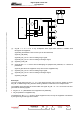
- status and command data regarding the power amplifiers,
- sensor status data both from the sensors in the protection system and from various other
sensors.
• it terminates the -12 V/+5 V DC input power supply from the exciter/CPU interconnection card,
• it accepts the transmitter start and stop commands,
• its output signals are as follows:
- presence data regarding the power amplifiers and their power supplies,
- mains presence data from the Mains Distribution Panel,
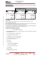
♦ connector J14, which by being connected to connector J6 on another multiplex card allows the
Central Processing Unit to be connected to several multiplex cards in parallel,
♦ input connector J7, for status signals from sensors,
♦ connector J8, which sends additional status data from the sensors to the Central Processing Unit,
♦ connector J10, which accepts the Sound AGC voltage from another multiplex card (used on an
analogue transmitter with split channels),
♦ connector J11, which sends the Sound AGC voltage to the exciter cards (used on an analogue
transmitter with split channels),
♦ connector J12, which accepts the AGC voltage (specifically the vision AGC voltage on an analogue
transmitter with split channels) from another multiplex card,
♦ connector J13, which sends the AGC voltage (specifically the vision AGC voltage on an analogue
transmitter with split channels) to the exciter cards,
♦ connector J15:
• sends the cooling On command to the cooling system,
• and receives the signal quality status data from an external measuring device,
♦ connector J16, which accepts the switched DC status signals for extraction/insertion of the power
amplifiers,
♦ connector J17, which accepts certain other status signals from sensors; these signals have no
connection with the protection system.
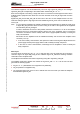
3.13.8. Power input
The multiplex card is fed with -12 V DC from the exciter power supply card(s).
An internal voltage regulator provides the main power supply at -12 V/+5 V to the multiplex card.
The +5 V DC powers supply from the CPU power supply card is also used by some internal circuits.
These power supplies are fed from the exciter/CPU interconnection card via connector J6.
3.13.9. Cooling
The multiplex card is cooled by natural convection.