
Operation Manual Part 3


Digital Liquid Cooled UHF
TV Equipment
Description / Test points / Location of units
9946 V1
45321648.01 104 A E
preliminary
110 / 131
Numéro / Number Doc. Rev. Lan
g
u.
16/06/2006
Pa
g
e
Information contained is this document is confidential, is THOMSON property and cannot be disclosed in whatever form without prior written authorization of THOMSON.
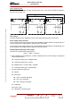
3.13.4. Indicator lamps and message displays
If the internal +5 V from the internal regulator on the multiplex card is faulty or missing the following
indications are given:
♦ the green LED. "DS3" is extinguished,
♦ the message "UNKNOWN" is displayed in the "PSU n" message windows in the PCL "POWER
SUPPLY" window.
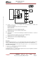
3.13.5. Protection and surveillance devices
The multiplex card has a monitoring circuit for its own internal power supply.
It has protection devices ahead of the -12 V/+5 V regulator as follows:
♦ F2: protects the -12 V supply from the exciter A power supply card,
♦ F3: protects the -12 V supply from the exciter B power supply card.
These fuses go open circuit in over-current conditions and reset automatically; they cannot be
changed on line.
3.13.6. Adjustment controls
The card has no adjustment controls.
ATTENTION :
There are switches on the multiplex card to configure the transmitter and also to set up
certain operational parameters in relation to the amplifier power supplies. These
jumpers and switches are factory-set and should not be repositioned.
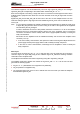
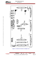
3.13.7. Connections and data transfer
The multiplex card has the following connectors:
♦ connectors J1 to J5 which function as follows:
• they connect the data exchange bus between the amplifier power supplies 1 to 5 on the one
hand and the exciter/CPU interconnection card on the other; these data consist of:
- amplifier power supply status data,
- status and command data regarding the power amplifiers,
• their input signals are as follows:
- on and off commands for the multiplex cards,
- AGC voltages,
- removal/re-insertion status signals from the amplifier cards,
• their output signals are as follows:
- presence data regarding the power amplifiers and their power supplies,
♦ connector J6 which functions as follows:
• It connects to the data exchange bus to the Central Processing Unit, via the exciter/CPU
interconnection card; the data exchanged are as follows:
- amplifier power supply status data,