
Operation Manual Part 3


Digital Liquid Cooled UHF
TV Equipment
Description / Test points / Location of units
9946 V1
45321648.01 104 A E
preliminary
108 / 131
Numéro / Number Doc. Rev. Lan
g
u.
16/06/2006
Pa
g
e
Information contained is this document is confidential, is THOMSON property and cannot be disclosed in whatever form without prior written authorization of THOMSON.
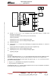
The selected equipment unit will simultaneously send both logic signal DN_ANA_BA and analogue
signal DN_ANA_BA corresponding to the number within address AD_BA < 0…3 >.
Each of these signals is sent along a single wire which is connected to all the equipment units via the
multiplex board; equipment units which have not been selected via the CS_BA signal will not return
any signal.
Signals DN_INF_UB and DN_ANA_UB are then sent to the CPU via the multiplex board. The CPU
reads the analogue signal or logic signal and then disables signal CS_UB in order to indicate the end
of the cycle.
Note : If a non-selected equipment unit exhibits a malfunction with regard either to signal DN_ANA_BA or
to signal DN_INF_BA there will be incorrect routing to the CPU of the signal from the equipment
unit selected by the CS_UB signal.
In order to determine the source of this problem, disconnect connectors J1 to J5 on the multiplex
board and check for normal signal transfer with the rest of the equipment; then re-connect the
connectors one after the other to identify which Power supply/Amplifier assembly is causing the
faulty communication.
Disconnect the two amplifiers from the identified assembly and reconnect the multiplex board
connector (J1 to J5).
♦ In the case of faulty communication, first replace the cable connecting the multiplex board to the
power supply and the power supply itself in order to identify the faulty component.
♦ In the case of correct communication, interchange the two amplifiers in order to identify the
faulty component.
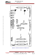
Write Cycle
The CPU sends the signal AD_UB < 0…10 > to start the write cycle via signal RW_UB; it sends the
command signal via signal DN_COM_UB and validates signal CS_UB before sending validation
confirmation to the multiplex board.
The multiplex board transfers the status of signal DN_COM_UB to signal DN_COM_BA.
The multiplex board then decodes the number the signal AD_UB < 0…10 > via the PAL unit and
generates the following signals:
♦ AD_BA < 0…3 > (identification of an equipment unit parameter),
♦ CS_BA (selection of equipment unit),
♦ The CPU holds signal CS_UB for 10 ms to indicate the end of the write cycle while the multiplex
board disables signal CS_BA.