
Operation Manual Part 3


Digital Liquid Cooled UHF
TV Equipment
Description / Test points / Location of units
9946 V1
45321648.01 104 A E
preliminary
106 / 131
Numéro / Number Doc. Rev. Lan
g
u.
16/06/2006
Pa
g
e
Information contained is this document is confidential, is THOMSON property and cannot be disclosed in whatever form without prior written authorization of THOMSON.
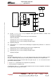
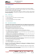
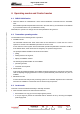
With 3 multiplex boards:
In case of converter G1 failure, the first converter takes over. In case of first converter G1 failure the
second converter takes over.
04/020 (e)
G1(1)
OUTPUT
MULTIPLEX
BOARD 1
INPUT
+ 5V
+5V
G1(2)
OUTPUT
MULTIPLEX
BOARD 2
INPUT
+ 5V
+5V
G1(3)
OUTPUT
MULTIPLEX
BOARD 3
INPUT
+ 5V
+5V
AGC voltages
The AGC voltages for each amplifier are fed to an OR gate before being sent to the exciters.
Power Supply voltage detection
As soon as the power supply voltage for the vision amplifiers has been detected, the signal PRE_ALI
(vision amplifiers power supply presence signal) is sent to the exciters.
As soon as the power supply voltage for the sound amplifiers has been detected, the signal PRE_ALS
(sound amplifiers power supply presence signal) is sent to the exciters.
Multiplexing/Demultiplexing of data signals
The name for a signal has the following format :
< Root > < Suffix > < Number >
♦ Each equipment unit is identified by a number. Numbers are also used to identify the equipment
unit internal parameters.
UB : Central Processing Unit
⇔ Multiplex board.
UE : Central Processing Unit
⇔ Exciter.
BA : Multiplex board
⇔ Power Supply – Amplifier.
UA : Central Processing Unit
⇔ Display Board.
♦ The root identifies the signal type:
AD : Address
DN : Data signal
DN – COM : Command data signal.
DN – INF : Logic read signal.
DN – ANA : Analogue read signal.
CS : Chip Select.
RW : Read – Write.
INI : Initialisation in progress signal.