
Operation Manual Part 3

Digital Liquid Cooled UHF
TV Equipment
Description / Test points / Location of units
9946 V1
45321648.01 104 A E
preliminary
105 / 131
Numéro / Number Doc. Rev. Lan
g
u.
16/06/2006
Pa
g
e
Information contained is this document is confidential, is THOMSON property and cannot be disclosed in whatever form without prior written authorization of THOMSON.
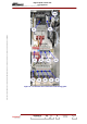
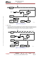
The selection of starting steps order is configured via switches: S401, S402 and S403 on multiplex
board.
Cabinets which have more than 10 amplifiers have two multiplex cards as follows:
♦ one of them is associated with 8 amplifiers and the total protection system,
♦ the other is associated with the remaining amplifiers and its protection system only monitors the
station protection system while the other surveillance device contacts are short circuited by a strap.
♦ The opening of the contact on the by-stable relay K1 by activating the "OFF" command which
comes from the exciter/CPU interconnection card switches off the +5 V supply which controls the
optical relays (K4 to K10). The opening of these relays switches off the amplifier power supplies
and the cooling system.
Protection system
Each cabinet has its protection system; it consists of sensor contacts which are connected in series in
the multiplex card. The open circuiting of just one of these contacts is enough to open the relays which
control the mains feeds to the amplifier power supplies and the cooling system.
When the transmitter is started up and the cooling is switched off, the "cooling air pressure correct"
signal is simulated in order that the associated surveillance device does not prevent the switch-on of
the amplifier power supplies.
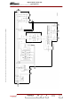
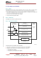
+5V_DC redundancy
This redundancy is available (whatever the defected converter) only with cabinet with 2 or 3 multiplex
boards.
In case of 3 multiplex boards, only one redundancy is possible.
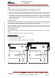
With 2 multiplex boards:
In case of first DC/DC converter G1 failure:
♦ contact of relay K401 toggles,
♦ second converter G1 supplies system with +5V_via fuse F402.
G1
OUTPUT
INPUT
+ 5V
+5V
G1
OUTPUT
INPUT
+ 5V
+5V
04/019(e)
MULTIPLEX BOARD 1
MULTIPLEX BOARD 2