
Operation Manual Part 3

Digital Liquid Cooled UHF
TV Equipment
Description / Test points / Location of units
9946 V1
45321648.01 104 A E
preliminary
87 / 131
Numéro / Number Doc. Rev. Lan
g
u.
16/06/2006
Pa
g
e
Information contained is this document is confidential, is THOMSON property and cannot be disclosed in whatever form without prior written authorization of THOMSON.
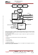
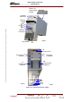
Fixed
attentuator
Variable
attenuator
Phase
shifter
Gain
control
Temperature
compensation
&
protection
SWR protection & storage
Overcurrent protection &
stora
g
e
OR
Power supply
-10V
+5 V
+12V
+28V
+30V
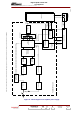
Fault detection
Auto-diagnostic
system
Input power
Output power
Current fault with/without Pw
SWR fault
Overcurrent fault
Power supply fault
Temperature fault
Amplifier fault
Reset
Reset
Reset
Power supply protection
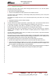
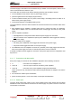
All the above fault signals, i.e. VSWR, overcurrent and temperature are sent to the Central Processing
Unit card after validation. Validation consists of checking the internal supplies (+5 V and -10 V) and
the external supplies (> 24 V).
The auto-diagnostic «amplifier fault» signal is a logical 1 output from a logical «Or» gate with the
following fault inputs :
♦ VSWR,
♦ transistor over-current (measurement of current of 2 amplifier modules),
♦ temperature,
♦ RF transistor failure,
♦ low RF power output,
♦ internal power supply fault.
The absence of an external power supply fault (> 24 V) validates the auto-diagnostic system and
sends the validation signal to the CPU card.