
Operation Manual Part 3

Digital Liquid Cooled UHF
TV Equipment
Description / Test points / Location of units
9946 V1
45321648.01 104 A E
preliminary
104 / 131
Numéro / Number Doc. Rev. Lan
g
u.
16/06/2006
Pa
g
e
Information contained is this document is confidential, is THOMSON property and cannot be disclosed in whatever form without prior written authorization of THOMSON.
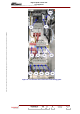
CURRENT
LIMIT
+ 5V_CHS
SECU_STA SECU_ARM SECU_PRINCIP PRES_SECT TMPH SECT_VENTIL SECT_VENTIL_EX
RELAY
K1
ON
DELAY 1
AIRLIQUID
1 - POWER
SUPPLY ON
"OR"
GATE
(DIODES)
Cooling ON
(not used)
Mains presence
3 - POWER
SUPPLY ON
&
RF CONTROL(s)
to EMB
DELAY 2
2 - PRESSURE
SWITCH
SECURITY
04/017 (e)
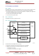
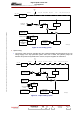
Figure 23 : Air cooling system
♦
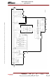
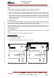
Liquid cooling:
• The closing of this contact by activating the “ON” command enables the transmission of the +5V
voltage supply to the loop protection system and if this is closed, the hydraulic pumps are
switched. Only when the hydraulic flow is correct, the power supplies are switched on.
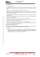
CURRENT
LIMIT
+ 5V_CHS
SECU_STA SECU_ARM SECU_PRINCIP PRES_SECT TMPH SECT_VENTIL SECT_VENTIL_EX
RELAY
K1
ON
DELAY 1
AIRLIQUID
3 - POWER
SUPPLY ON
"OR"
GATES
(DIODES)
Mains presence
4 - RF CONTROL(s)
to EMB
DELAY 2
2 - FLOW METER
SECURITY
Hydraulic system
04/018 (e)
1 - COOLING ON
Hydraulic system
AIR COOLING
(no used)
Figure 24 : Liquid cooling system