
Operation Manual Part 3

Digital Liquid Cooled UHF
TV Equipment
Description / Test points / Location of units
9946 V1
45321648.01 104 A E
preliminary
102 / 131
Numéro / Number Doc. Rev. Lan
g
u.
16/06/2006
Pa
g
e
Information contained is this document is confidential, is THOMSON property and cannot be disclosed in whatever form without prior written authorization of THOMSON.
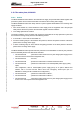
3.13. The multiplex card, 45324500
3.13.1. Outline
The multiplex card is the main connection distribution centre for the bay in which it is installed. It is the
central routing hub for input/output connections for status and command data circuits between:
♦ the Central Processing Unit on the one hand and the amplifiers, the amplifier power supplies and
the sensors (excluding the probes) on the other hand,
♦ the exciter cards and the amplifiers (AGC voltages),
♦ The UC card and the hydraulic cabinet.
3.13.2. Architecture
The multiplex card consists of a printed circuit card.
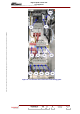
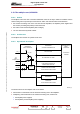
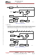
3.13.3. Operational description
-12V (B)
DC/DC
MUX/DEMUX
CPU-SUB ASSEMBIS DATA
DETECTION AND PRESENCE SIGNALS
FOR POWER SUPPIES TO
POWER AMPLIFIERS RF
AGC VOLTAGE
BLACK/WHITE VOLTAGE
POWER COOLING SYSTEM
LOOP PROTECTION SYSTEM
INTERFACE
LOOP PROTECTION SYSTEM
MUX/DEMUX
POWER SUPPLY
AMPLI.
INTERFACE
INTERFACE
UNITE CENTRALE
+ 5V_U
-12V (A)
04/021 (e)
+ 5V
Other
multiplex board
+ 5V_DC
HYDRAULIC
CABINET
The main functions of the multiplex card are as follows:
♦ transmission of commands from the Central Processing Unit to the amplifiers,
♦ multiplexing and transmission to the Central Processing Unit, of data from:
• the amplifier power supplies,
• the amplifiers (via the amplifier power supplies),