
Operation Manual Part 3

Digital Liquid Cooled UHF
TV Equipment
Description / Test points / Location of units
9946 V1
45321648.01 104 A E
preliminary
100 / 131
Numéro / Number Doc. Rev. Lan
g
u.
16/06/2006
Pa
g
e
Information contained is this document is confidential, is THOMSON property and cannot be disclosed in whatever form without prior written authorization of THOMSON.
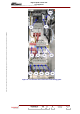
3.12.2. Indicator lamps and message displays
♦ An orange indicator lamp on the mains monitoring relay K1 gives further information on the
incoming main supply as follows:
• Lit up : OK,
• Extinguished: absence or inversion of phases.
♦ E1 includes 4 surge arrestors “over voltage protection” ( 3 between Phases and Ground , the 4 th.
one between Neutral and Ground .When one surge arrestor is damaged, the light on the
corresponding arrestor is on : the plug-in module has to be replaced .
3.12.3. Test points and adjustment controls
The front panel of the Mains Distribution Panel does not have any test points or adjustment controls,
which can be used by the operator.
3.12.4. Protection and surveillance devices
Refer to the preceding section «operational description of the Mains Distribution Panel».
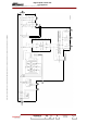
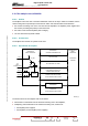
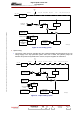
3.12.5. Connections and data transfer
The input connections to the mains distribution panel are used to determinate the incoming phase
voltage and earth.
The output connections are as following :
c
Cables for feeding three phase supplies to the amplifier power supplies.
d
Signal link cable allows to forward the surveillance status data of the main circuit breaker in the
Central Processing Unit via TB2 to roof interconnection J3.
e
Signal link cables allows to forward the surveillance status data of mains (phase detector) in the
Central Processing Unit via TB2 to roof interconnection J3.
f
Signal link cables allows to forward the surveillance status data of mains (over voltage) in the
Central Processing Unit via TB2 to roof interconnection J3.
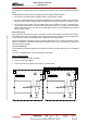
g
Cable for feeding single phase to the SIRIUS 1.
h
Cable for feeding single phase to the SIRIUS 2.
i
Cable for feeding single phase to the very low voltage power supply for the screen of the
control panel via the gestion rack
j
NU
k
Cable for feeding single phase to the very low voltage power supply for the Control Processor
Unit via the management rack
l
Cable for feeding single phase to the exhaust fan on the roof.
NOTE : A connector TB1 allows to modify the Input mains configuration for feeding Sirius and
Screen of Control panel. This elements can be fed by an uninterruptible power supply
(UPS) via the circuit breaker Q5 (noted
{option) or fed by the emergency mains input .
Both temperature informations ( input and output) are connected on terminal block TB2 .