
Operation Manual Part 3

Digital Liquid Cooled UHF
TV Equipment
Description / Test points / Location of units
9946 V1
45321648.01 104 A E
preliminary
95 / 131
Numéro / Number Doc. Rev. Lan
g
u.
16/06/2006
Pa
g
e
Information contained is this document is confidential, is THOMSON property and cannot be disclosed in whatever form without prior written authorization of THOMSON.
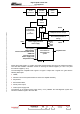
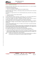
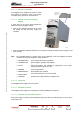
The mains supply to the module can be switched off by an isolator on the front panel ; fuses F1 to F3
can be accessed when the isolator is open.
The control card has a mains circuit with the following protection and surveillance devices:
♦ a current limitation circuit which is active on power supply start-up,
♦ protection against mains overvoltages (surge arresters),
♦ a mains surveillance device (loss of a phase, under-voltage, overvoltage) which can switch on or
switch off the power supply module,
♦ an EC (Electromagnetic Compatibility) filtering circuit.
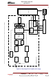
The output interface card has a switch on/switch off circuit which monitors the connection status of the
amplifiers :
♦ Each amplifier has the capability of sending data when it is present and when it is withdrawn.
These data in addition to the On command (shut-down circuit) trigger the start-up of the power
supply,
♦ when an amplifier is withdrawn :
• the disappearance of the presence data causes the power supply to be shut down,
• after the extraction of the amplifier the opening of the withdrawal contact triggers the restart-up
of the power supply,
♦ during the insertion of an amplifier :
• the closing of the withdrawal contact triggers the shut-down of the power supply,
• the presence data triggers the switch on of the power supply,
♦ The withdrawal of the two amplifiers connected to a particular power supply triggers the total shut-
down of the power supply even if the on command (shut-down circuit) is continued.
A thermal surveillance device triggers the shut-down of the power supply when the temperature rises
beyond 75°C.
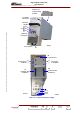
3.11.1.7. Connections and data transfer
Each power supply is connected to other installation equipment via the following connectors :
♦ J1 : connections to the multiplex card,
♦ J2 and J5 : +30 V DC output connectors to feed the power amplifiers,
♦ J3 and J6 : connectors on the power amplifiers of high power transmitters.
These connectors carry command and status data exchanges between the multiplex card and the
amplifiers,
♦ not connected on medium power transmitters,
♦ power connector (phases 1, 2 and 3 and earth) : mains input feed termination.
3.11.1.8. Power input
The three phase mains input supply is fed to each amplifier power supply module from the Mains
Distribution Panel. Each module is connected to the mains supply via a power connector on the back
of the module, in the bottom.